Background:
About a fortnight ago I found that the X axis would occasionally start to creep as I watched. This would be a few 10s of microns every few seconds but that would add up over the course of several minutes to a noticeable fraction of a whole mm. So although it wasn't exactly a case of the axis running away on me, it would severely fuck up anything I tried to machine. It seemed to have a fairly random nature, which strongly suggested an electrical noise issue. I somehow doubt that the controller would be putting out random step signals.
I was able to rapidly narrow down one of the key elements of the issue. I removed the link between the cabinet ground and the logic ground. This significantly improved the situation but it didn't eliminate it. I then found that fitting a large toroidal core over the axis connector (where the step, direction etc signals come out of the controller) eliminated the remaining noise.
Although this large toroid seems to have done the trick, it's not the best solution, so I got some Chinesium clamp-on ferrite filters of unknown parentage off ebay. These are often seen on computer cables, power supply leads etc and are simple enough to clamp over existing cables without needing to disturb solder joints etc.
Given that I clearly have some marginal noise issues, I'll go around the various signals cables and see if I can discern any improvement resulting from fitting these things, starting with swapping out said toroid for a Chinesium clamp-on jobby.
In the end, I managed to fit all 10 of these things, along with a couple of almost identical ones from my box of cables - these ones from a couple of Ethernet cables of unknown heritage. They even fit over the lurid green drag cables. And they are pretty neat.
Step back a bit, Fatty:
Just like the servo drives on The Shiz, there is some level of noise on the X and Y axis drives on the Bridgeport. You can feel a low level grumbling on the ballscrews when the system is powered up. And given that this must surely imply some degree of movement of the motor, it can't be ideal. I'm guessing that the encoder feedback keeps the final position under control but it would be better if there was no noise to compensate for to begin with. This could be a common (normal?) problem with both (all?) installations.
Who knows, it may even be possible to improve on the installation on The Shiz itself. But let's see how we get on with the BP first, before we start getting too clever with ourselves....
Soooo - any better?
Certainly, it seems to sound a bit quieter. That migth be because I'm half expecting it to but certainly, when not at being asked to move, the motors are totally silent and there is only the vaguest hint of that electrical noise / quiet grumbling you almost always get on motor / drive systems. And if you try to move the servos around their set position, the zero error position where said noise happens seems to be very localised and the grumbling very gentle. Technical term there.
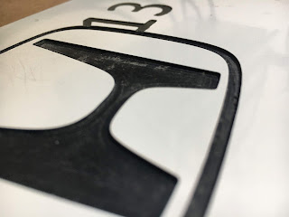
Anyway, let's repeat the Honda logo engraving job and see how we get on. Last time we were seeing stepped changes in the height of the engraved areas, to the point where the tool had lifted beyond the top of the material. The MCS machine origin had crept up, as could be seen in the return height of the quill.
So here's the acid test. For comparison, here's the previous example from 2 different angles:
The steps are quite evident.
...and here's the latest example. Looks pretty convincing to me. You can see the toolpath but there are none of the unintended steps in the height of the (machined) black surface.
This may not be quite up to professional levels of proof but I'm fairly confident that I've likely fixed the issue. The next proper job will involve machining some of your actual metal, so I will reserve 100% judgement until then. But for now, The Stupid Fat Bloke is pestering me to get on with something more exciting. For once, that seems reasonable to me.
Retrofitting 1983 Shizuoka AN-SB CNC milling machine, Bridgeport mill, Colchester Bantam lathe and 1982 Tree UP-1000 CNC lathe with modern controls - and other workshop stuff
Subscribe to:
Post Comments (Atom)
End stop for drawer self closing damper
Que? We have a couple of these pull out spice drawers in the kitchen. They are 150mm / 6" width and are basically filling in a 30cm gap...

-
Setting up the servo tuning(?) software: Having spent a couple of hours yesterday pratting about with the PID controllers for the X and Z ax...
-
Right, so having gone through the motions with the X axis (cross slide), I should now be able to set up the Z axis (longitudinal) encoder an...
-
The bearing arrived as expected this morning. Took a few minutes to make up a 42 x 25.5 x 7mm thrust washer, then fitted the bearing and was...


No comments:
Post a Comment