When I had the original (Newker 990 MDCa) controller fitted to The Shiz, I tried out the 4th axis feature. Given that the controller I bought was the 4 axis version and I'd acquired a 4th axis from the (now late) John Stevenson, it would have seemed rude not to have checked it out.
For this, I coughed up for a simple open loop stepper driver from ebay. This was the DM556, allegedly from Leadshine. In fact, when it arrived, I did a teardown of the Leadshine stepper driver and it actually gave the appearance of being the real item. What the hell, it was about the cheapest option to get me going.
For the stepper motor, I went for something from Zapp Automation, simply because they had it in stock and I wouldn't have to wait for weeks on the slow boat from China - and get ripped off on the way into the country.
Couldn't help taking a peek inside it while I was fettling it up to fit in place of the original motor.
Finally got it working but despite no end of buggerage, I couldn't get it do do anything sensible in true simultaneous 4th axis mode. The "non-simultaneous 4th axis mode" (aka indexing) worked OK but that's not much to write home about and certainly not worth all that effort.
In the end, I made my excuses and left, figuring that either the controller was crap and / or the Fusion 360 post processor required some further development. Either way, I wasn't going to be able to much to fix it myself.
What's changed then, Fatty?
Well for one thing, the post processor has 2 more years of water under the bridge. And secondly I have a new controller in the Centroid Acorn, which gives the appearance of being able to support 4th axis. Judging by others, this should be fairly mature now. As I've sort of completed the Bridgeport conversion for the time being, it's time to gadfly over to The Shiz and play with the 4th axis.
So, out with the stepper drive (which I'd mounted in the cabinet of The Shiz for just this outcome) and the 4th axis itself. First, get it set up and working on the bench, before hoisting the damned thing up onto the table. I'll need to engine crane to do that safely, as it must weight around 50kg or so. Yes, bastard heavy, no matter how you look at it.
No need for a long story here but here's the final config page from the Acorn wizard. The funny ratio is something to do with the weird pulley ratios I used (something like 19th driver, 24t driven, IIRC) and the reduction ratio in the rotary table of unknown parentage.
Checking the rotation over something like 10 turns, it seems to be pretty much spot on. And the feed rates are trial and error, with a little bit of safety margin to account for loaded operation.
Ready for action?
So we seem to have a goer here. At this point I might be tempted to tidy up all the wiring and reinstall the stepper driver in the cabinet but I'm not convinced I want to do that. For one thing, I'm thinking of acquiring a harmonic drive and possibly a servo motor and driver. And I'm not convinced the shitty Chinesium stepper motor and its Leadshine(?) friend are going to work sensibly. So for now, I'll stick with the lashup arrangement.
Also, the 4th axis itself is fucking massive, with a height of around 15" or so, which presents a real risk of collision with the quill / spindle / head.
Ideally, I'd mount it on the left end of the table but this is where I am currently homing the machine. Which means that crashing it into the head would be a fairly obvious outcome. I'm also getting rather sick of having to dodge the end of the table when the machine is parked. Currently, the home position is at the negative X extent ie the table ends up at its far right extent.
Changing the X home position:
To change the X home position to the other end of the table, I need to:
- Change the cncm.hom (hole) file, most easily by using the wizard.
- Move the home switch trigger target so that it triggers before the hard limit switch(!). In my case, I left The Stupid Fat Bloke to fit the targets on the underside of the table and he got them the wrong way around. So although it tries to home correctly, it hits the +L switch before the home switch - and stops of course. Gah!
So the first task is to reposition the home target a couple of cm further in - or the limit switch a few cm further out.
Viewed from the RHS of the table:
And viewed from the other (ie LHS):
The outermost switch is -L, the next is +L, then the home switch.
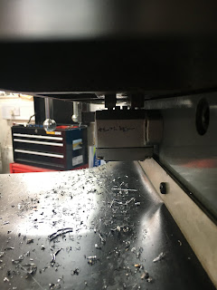
Here's the world's best photo of the underside of the table, showing the offending stops:
I am deducing that the top one (with dual ramps, closest to the slideways) is the home switch and the other one is the limit switch. Surely they are arse about face, as you'd want the home switch to be dual ramp on a good day. I may need to think about that more closely tomorrow. It's been a long day.....


No comments:
Post a Comment