First, chop up some loominum. This is some 6061 I got in Canada. Using The Shiz in manual mode, using the MPG to move the tool and table. I'm not about to spend hours of my life doing this in Fusion. Let's try to be sensible here.
That Korloy face mill with APGT inserts does a fine job. If you look closely, There's an interesting(?) interference pattern caused by overlap of the leading and trailing edges of the tool. This is due to my manual operation of the MPG, resulting in variation in the tool speed across the workpiece. You wouldn't normally get this when using CNC mode / constant feed rates etc.

Being careful to ensure the surfaces are square and the 3 blocks end up the same size.

It's a "90 degree" cutter, so cuts nice shoulders too. I'm always shitting myself when holding multiple parts in the vise like this, as you can't be certain all three parts are actually being clamped equally. A loose part could send a part through the window, destroy the tool and fill my underwear with mud.

4mm carbide end mill at 5000rpm to create the slots, stopping occasionally to prevent recutting / tool breakage. Mostly, the swarf was ejected in a stream, so didn't need to do much of that:

Then drill and counterbore the various holes for the fasteners and deburr with the Noga tool.

Once I'd found suitable fasteners, it all just bolted together. It happens sometimes.

The two studs are the targets for the proximity switches. These are the +L and -L limit switches. They are triggered by the "low" stud (nearest the scale).
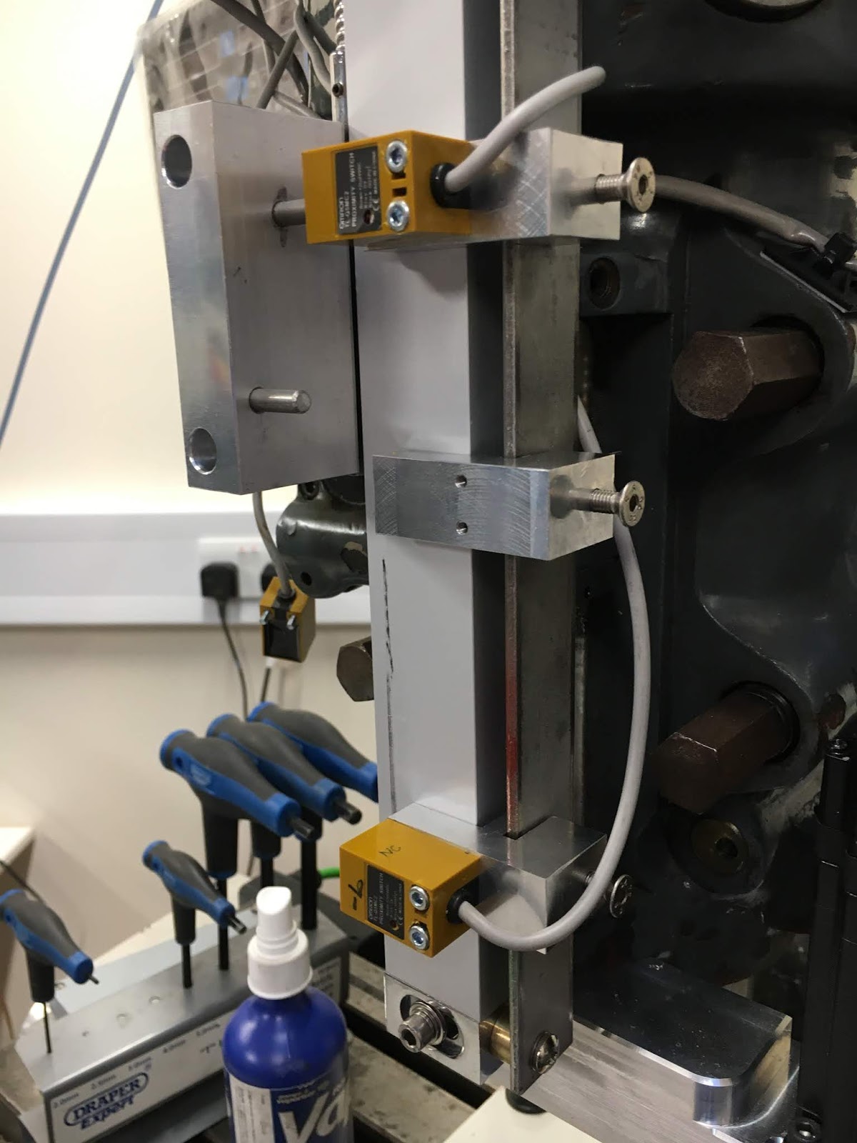
A 10mm spacer lifts the Z0 (home) switch so it is triggered by the higher stud.

Looks OK. It's not exactly up to professional standards but I can't be bothered to spend more time on this than necessary. It should do the trick.

Reminder - if you don't fully tighten the ballscrew nut, it will fall off (along with the key) when you start to exercise it. Luckily I had milled some 12mm flats on the ballscrew and a couple of holes in the nut for this circlip tool.

Setup - what is the end result?
Part of the plan was to maximise the range of movement by allowing a larger range of movement for the proximity switches without them hitting something. So the last part of the setup is to set the positions of hardware limit switches (+L and -L) at the physical extents of movement, then program suitable software limits, then set the home switch position.
Obviously you need to set the limit switches somewhere short of the point at which the mechanism hits some form of hard stop. And the home switch needs to be seen before the hardware switch is activated. All in all, the practicalities of switch operation etc mean that you end up with less software programmed travel than the extents of physical movement.
With the classical Bridgeport quill setup, you can just about manage 125mm (5") of movement in manual mode. So something like 115mm of software limited movement would be a great result. In the end, I managed 110mm, to avoid running into the hardware limit. The alternative would have been to slow down the home seek speed, to reduce the overshoot and thus gain a few mm of home position. 110mm will do for now and it's almost an inch more than the 90mm I had with the old system.
What's next? Good. Now that's in place I can move on:
- Check the calibration of the controller - how does the controller DRO compare with the glass scale DRO, which I take as the word of god here?
- Get an idea of the backlash. So far I'd estimate about 50-75um ie 1-2 thousandths of an inch in old money. That's probably as good as I should expect.
- But above all, let's try to get to the bottom of the creep issue on the Z axis. After running the engraving program (Honda logo etc), I saw gained / lost steps. Now I have a means of catching it and investigating the cause and a suitable corrective action(s). Pretty sure the VFD noise was something to do with it....


No comments:
Post a Comment