I can't decide for certain but it almost reads as if the Newker 990MDCa controller is capable of accepting external encoders for actual position feedback of the table and quill. The setup screen seems to contain parameters relating to this in the parameter range #200-220 within the "Other" page. They relate to allowable positional error (between set position and actual) and scale resolution (um per pulse) for the glass encoder scales.
I'm not 100% convinced that the system is offering a means of closing the loop. I can't help suspecting that in fact this is offering no more than a means of displaying actual position on the screen and generating an error if the difference exceeds those specified limits. The Chinglish manual really doesn't give much of a clue, although there is no mention of any PID controller which rather leaves me suspecting it's simply a "display and compare" function. There's only one way to find out for certain....
Check it out:
Some time ago, I created an interface board for the DMM Tech encoders. That was little more than a standard bidirectional line driver IC on a board in a box. But it allowed me to tidy up the installation of the DMM Tech servos, which would otherwise have required a crappy 9 way D connector hanging off the motor. Hardly industrial quality and no easy way to make it coolant / swarf proof.
Here was the wiring table I created at the time. It also includes the schematic I implemented and the pinout of the IC itself. Notwithstanding the inevitable cockup on the layout (yes, The Stupid Fat Bloke was entrusted with that task), it actually worked well.
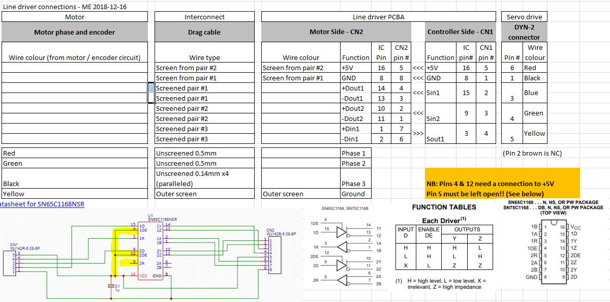
Conveniently, when I ordered the PCBs and kit of parts from JLCPCB and sister company LCSC, I got a set of 10 and built up half a dozen of them. Although I only printed up the required pair of housings, I don't need them to carry out this investigation right now.
This is it, marked up with suitable(?) names:

How to connect up?
Here's the pinout for the encoder feedback connections.


You will note that this is a 26 way connector, not a 25 way connector. So in fact, it's a high density subminiature D connector. The likes of which I don't currently have. Bollocks. And the connector wasn't supplied with the controller, as it's not usually connected up. And no - a VGA cable is no use. For one thing they are male connectors at both ends and for another, they are 15 ways.

For the DRO scales:
The other end of the puzzle is working out how to connect the (single-ended) TTL signal from the DRO scale reader head to my line driver board. I will have 2 TTL signals - one for X and one for the complementary signal. These line drivers have 2 lines going each way, so one board should suffice for one axis.
Here's the post showing what is inside the DRO display unit. With luck, I should be able to work out the connections from here without having to dismantle it again.
Here's the inside view. The 3 axis connections are at the bottom of the main board. For each there are 5 wires.
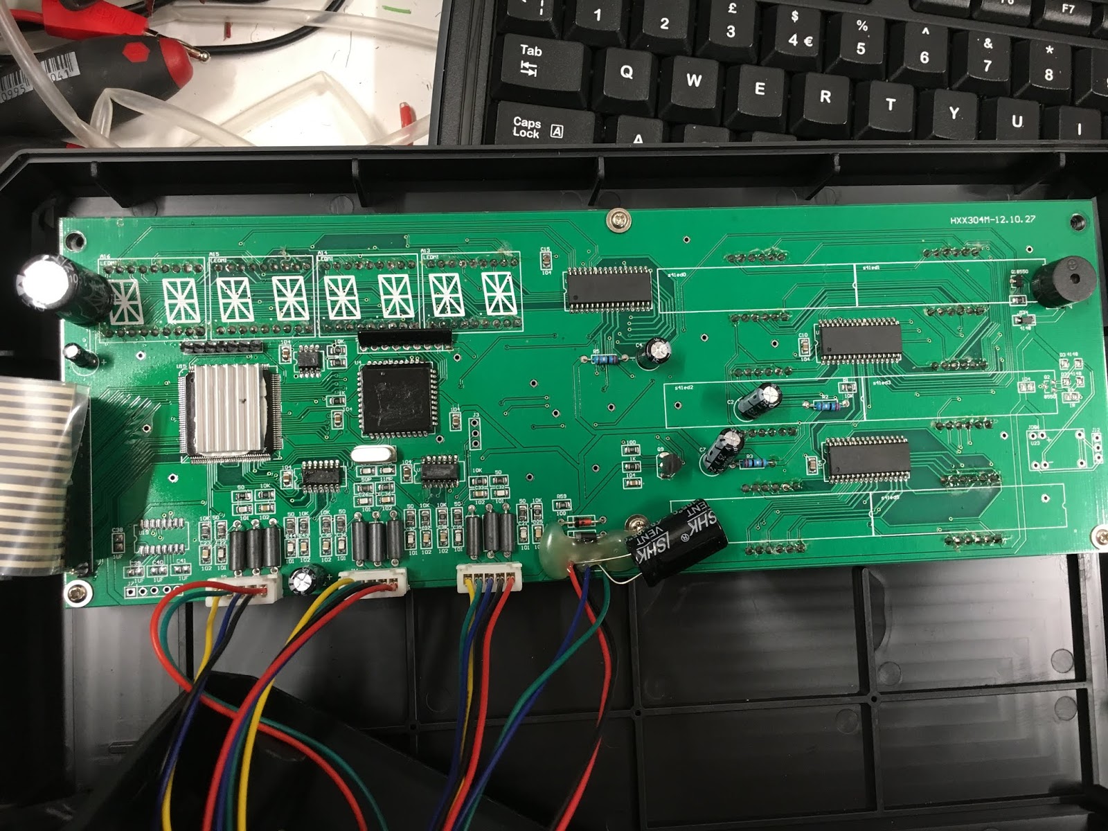
Inside the DRO display unit. Note that the ground / screen wire from the back of the connector is green, yet the connection to the protective earth is yellow. Go figure.

The pin allocation and wire colours are like this:

Strange "choice" of wire colour allocations!
Let's order some stuff:
Luckily, CPC stock these connectors at ~£0.87 each and can deliver next working day. Ebay also has some but the delivery would typically be around 5-10 working days. By then The Stupid Fat Bloke would have driven me round the bend with his impatience, so CPC it is, being cheaper (usually) than Farnell and RS.
But there's a min order value of £17.50 (before VAT) to avoid the £5 handling fee. And a £3 postage charge. So might as well get the value above £17.50 by adding some heatshrink tube, electrical contact spray, inrush current limiting NTCs etc.
Here's the 26 way high density Dsub connector from CPC Farnell. I seem to have some shells for that size connector, although I may never need them if this feedback isn't what I am hoping for.
I can take a cue from Centroid by using a similar spec for the inrush limiting NTC they use. CPC stock EPCOS (ex-Siemens) brand and my Bridgeport is a rather lower power machine than theirs, so I can afford to reduce the current rating somewhat. Here's the inrush limiter used on Centroid and the EPCOS equivalent from CPC Farnell. That should work.
That's me nicely upsold! Not much I can do until this stuff turns up, as there is no sensible way I can think to make connections to the CN13 connector on the back of the controller. Bollocks.
Hold on...
That whining from The Stupid Fat Bloke just got to be a bit much to handle, so we had a go at connecting up the Z axis linear scale in then end. Couldn't get the thing to talk at all, so to get something happening, I connected up a Heidenhain rotary encoder (a spare from one of The Shiz's brushed DC servo motors). This has complementary outputs for A, B & Z (index). Worked straightaway and the "position" signal came up in one of the optional DRO screens. But no, it doesn't attempt any kind of feedback. Instead, it simply displays the error between the current position and the target position. You can set a max allowable error and from what I can tell, it will pause the move instructions until the servo has caught up, then open the tap again.
Probably not a massive surprise but it constitutes the mild disappointment I was somehow anticipating. Buggerama and bastardisation. So at least I've answered that question, then. I may add a note to my version of the manual to sort of explain what I think we've got here.
Right, onwards and upwards onto something else.


No comments:
Post a Comment