Obviously if you have a short tool length and are planning to machine a deep feature, you won't succeed if the G54 Z0 position is beyond the reach of the quill movement and it will give you the "Z axis soft limit on line xxx" error message. At this point you are screwed until you fix the problem and the solutions are going to involve moving the work up or down (to change the G54 Z coordinate) or possibly reducing the retract etc heights and tool lengths.
Similarly, if you need to hold a large (ie long) drill in a typical drill chuck, the end of the tool will be a fair way away from the gauge plane.
So if you have a range of tools with wildly differing stickout distances and a variety of machining operations at different heights and machining depths that you plan to carry out on a knee mill, you will need to "get your sums right". Otherwise you get this bloody annoying bit of Chinglish telling you you have a problem with you soft limits (this example is actually caused by the failure of G28 but you get the drift):

I don't like to be particularly anal about stuff like this but on the other hand I hate frustrating surprises. So I thought in the long run it's probably best to do the job properly when it comes to setting up tools, heights, offsets, WCS positions etc. After all, it can't be that complicated. The controller only has a few Z dimensions to work with before it can say yeh or nay to the distances presented to it.
Seems to me I should be able to extract some info from the CAM setup (from the actual setup sheet and / or the CAM setup dialog boxes) and some tool length offset info from the controller - then do some basic sums to figure out the extent of Z moves required. Then be able to deduce the allowable range of quill positions for G54 Z0 (WCS origin) - if any - that will allow that range of movements.
Starting with the tool length offsetss - they are in the controller, having been acquired last week during the automatic tool legnth offset M882 macro. This gives the offsets for the tools I've got set up so far, spanning 2 screens:


Note that I have Tool 1 ("T01") on the first row. This is a dummy / reference tool which is just a bit of pointy 6mm loominum rod. I use this for checking positions, air cuts etc and roughly setting WCSs. If I have done my sums right, load T01 and tell the machine to go to G54 X0 Y0 Z0, the pointy bit should end up bang on the WCS origin. Cheaper than a cutter or a Haimer if you get it wrong.
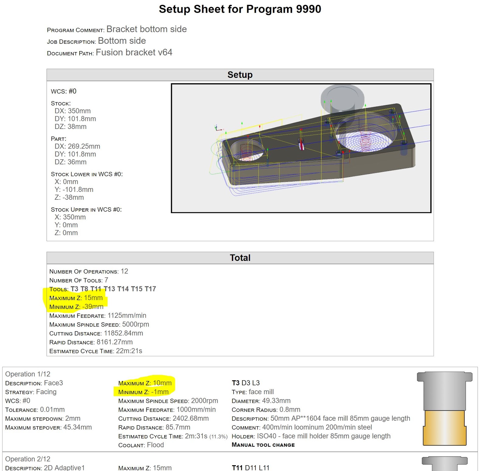
Then for the max and min X heights - these are actually summarised in the setup sheet that you can print out from the Fusion CAM environment.

Looks straightforward enough: Z heights ranging from -39 to +52mm. This covers the operations you have just posted but it's important to remember that if you are changing the WCS half way through the job, any subsequent Z heights will be taken from a different reference position. So for this job, I need to restrict the setup to the first 12 operations, covering the "bottom" of my part. So the range of Z heights is actually -39 to +15mm for this first setup:
Next we have to factor in the differing lengths of the tools in their holders. There is almost 100mm difference in the lengths of the longest and shortest tools.
The sums are quite simple:
If you add the tool length from the tool table to the Zmin and Zmax values for each combination of tool and operation, you will get the range of quill positions required to complete the operations with the tools you have programmed. The difference between the overall max and min values tells you the movement range for the quill, so if you know the movement that is allowable (between the soft limits, which will be slightly less than the physical range), you can see how much margin (if any) is available on the quill movement at the ends of travel. Furthermore, you can specify the position of the workpiece relative to the quill top position (G53 Z0). Typically for a machine like this with this range of tools, that will be a fairly small range of movement, so in reality I will have to move the knee up or down to get the work WCS origin into that height region.
Bottom line is - by doing some basic sums, you can set the height of the knee and the position of the quill (between specified limits) that will result in the controller giving the thumbs up. Of that's the plan anyway.
Here's the spreadsheet in its first iteration:

If I've got these simple sums right, I should then be able to load up the CAM for these first 12 operations and compile it without a problem.....


No comments:
Post a Comment