Whatever the time taken was, I'd guess that the vast majority of it (perhaps 75%?) was spend buggering about trying to get CAM settings to stick ie avoiding the annoying yellow triangle and "empty toolpath" message. The Mercans would call it "a steep learning curve".
One of the key frustrations was getting the chamfer function to work. There are 2 approaches to chamfering - either apply it at the CAD level or as a finishing operation during CAM. I prefer to have the CAD model representative of the final part, so that it goes into the CAD assembly and 2D compt drawings looking the way it will end up. But the CAM chamfering function seems to be much easier to apply to a sharp edge.
So having modelled the chamfers in the CAD model, I struggled manfully (but often in vain) to apply the CAM chamfer function to define the operation. As noted, it seems simple enough to apply to a sharp edge but how to implement a pre-chamfered (in CAD) edge?
1 - 2D Chamfer from a sharp edge:
This is the "simple" solution - where you apply a chamfer to a sharp edge. In this case, the hole is a countersink of 18mm major diameter on a bore of 10mm diameter. The tool is 12.7mm (ie 1/2" - bought in Canada) carbide tool. The dimensions are fairly critical, as achieving the true 18mm diameter would result in the countersink just touching the vertical wall. In practice I would want to leave a 0.25mm or so clearance so the tool doesn't actually touch.
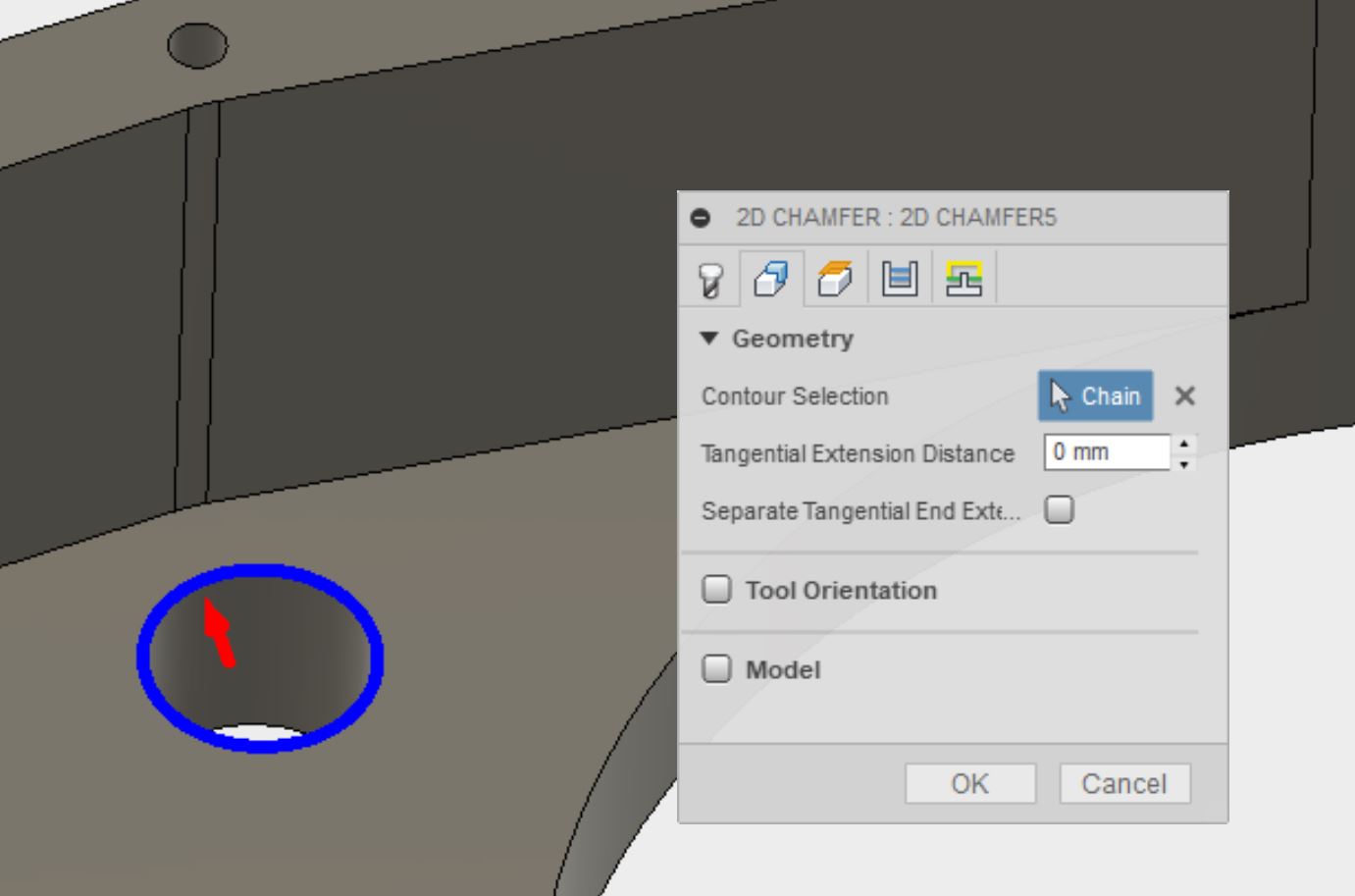
By default, the tip of the chamfer tool will be programmed to follow the blue profile you selected. Of course, you don't actually want the pointed tip of the chamfer tool to attempt any cutting, as it will always have zero surface speed, so you need to offset the point. It's simple enough to define an edge offset and doesn't need any explanation:

NB: To understand the numbers in this example, the plan is to get the circumference of the tool to just touch the larger circumference of the chamfer / countersink. So with a 12.7mm chamfer tool (radius 6.35mm) and a chamfer outer diameter of 18mm, you would need the tool to be offset by 2.65 mm. I've set it just below that, at 2.6mm, to give a gnat's cock of clearance.
In order to use this approach, obviously I had to delete the chamfer feature from the CAD model. The problem with that approach being that my CAD model no longer looks the way I want it to be and the CAD assembly will look crap and unrepresentative. So although I at least managed to get the end result, it's not an approach I want to use.
Collision avoidance in 2D Chamfer:
One nice feature of the 2D Chamfer tool feature is its collision avoidance. If you screw up the settings so that the tool would hit the work outside of the intended chamfer, it will limit the tool travel. So in the above example, if you reduce the tip offset, the tool shank would hit the vertical wall without collision avoidance. If you use one of the other methods described below, collision avoidance is not automatic. You have to check the simulation for collisions and finesse the settings either by trial and error or (ideally) by doing the relatively simple sums.
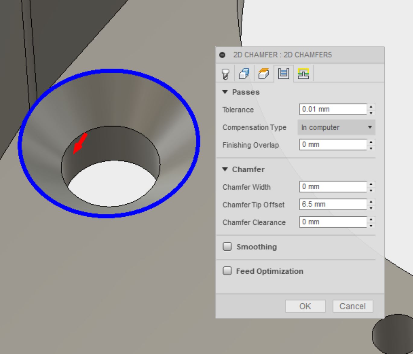
2 - 2D Chamfer starting from a CAD-modelled chamfer - using the "top" edge:
You'd think that applying a chamfer operation to a pre-modelled feature would be reasonably straightforward. But you might be wrong.
The chamfer tool locus descibes the path of the tip of the chamfer tool. The cutting speed at the tip is zero, so you need to offset the tip of the tool so that the cutting is done by the tool edge nearer the circumference of the tool. You never want to be using a chamfer tool with zero edge offset.
The tricky bit is getting the offset right. Too much and the tool will hit something outside the profile. And if it's a small hole / chamfer with a large tool, the lead-in / leadout distance and radius can be too large to fit in the space.
Note that you have to set the chamfer width as zero. It seems you aren't really chamfering so much as running a chamfer tool over an existing feature. I suppose that should have been obvious.

3 - 2D Chamfer starting from a CAD-modelled chamfer - using the "bottom" edge:
Sort of similar in many ways, you'd think. But again, with a pre-modelled chamfer feature, you need to run a "zero width" chamfer - and offset the tip "into" the bottom of the hole (in this example) to avoid tool collisions with the wall.

If you get it right, this is what you should end up with:
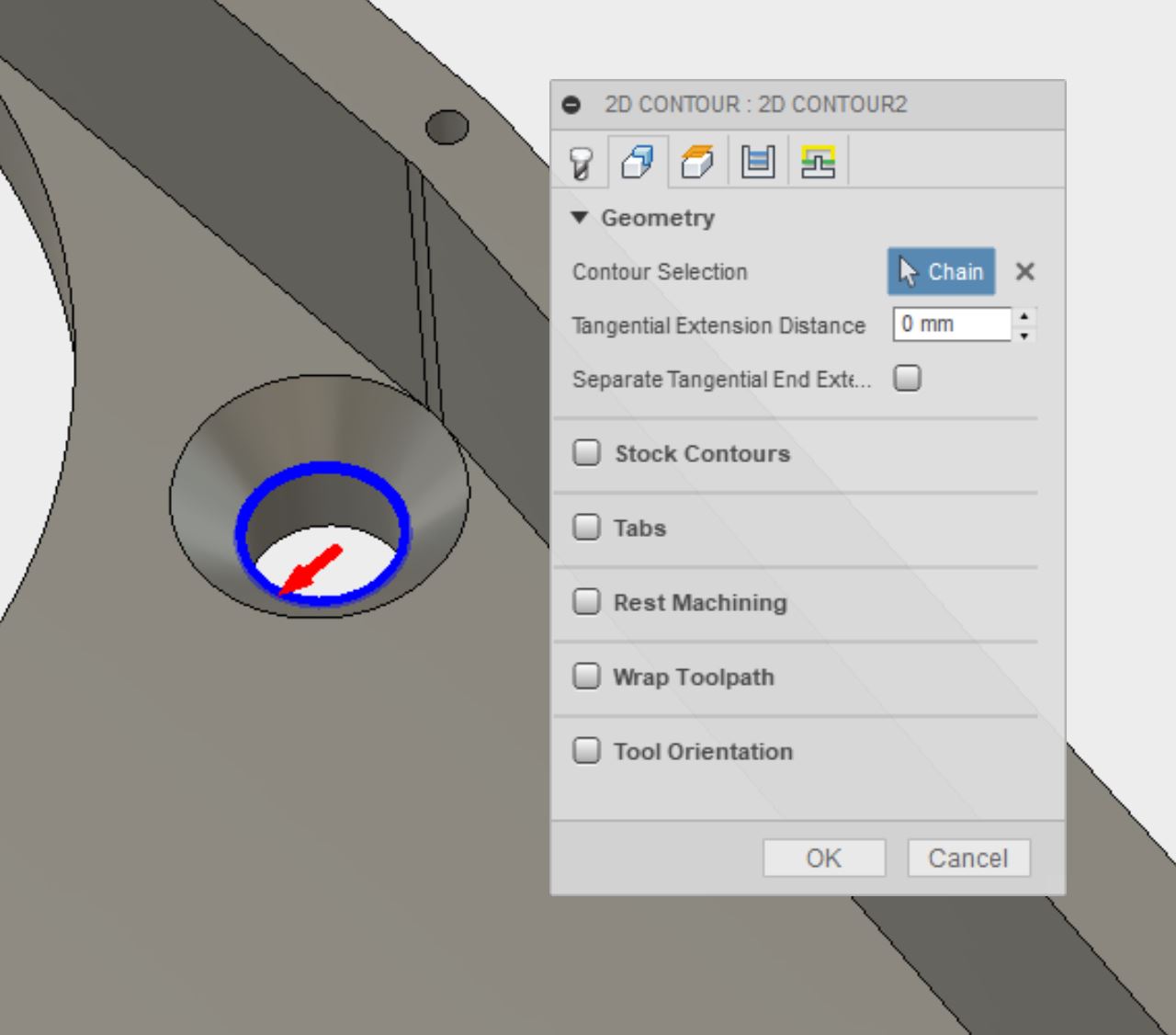
4 - 2D Contour - selecting top edge:
NB: Collision avoidance doesn't work for these operations. If you screw up the radial dimensions, Fusion won't help you and you may get a collision. You can check for collisions using the simulation tool.
The "tip offset" distance here is the distance between the tip of the tool and the selected edge - in this case it's the radius of the tool (6.35mm) plus a gnat's cock, giving 6.4mm. If you left the value at zero, the tip of the tool would follow the blue path and the 1/2" dia tool would want to go 1/4" into the vertical wall in this example.


5 - 2D Contour - selecting bottom edge:
Settings are quite simple. Again - chamfer width is zero and the "tip offset" parameter is used to position the tool.
If you left the tip offset at zero, the tip of the tool would follow the blue path, so the tool needs to be moved towards the hole centre by 2.65mm (difference between the 6.35mm radius of cutter and the 9mm radius of the larger chamfer diameter) - plus some margin, giving 2.5mm in this example.
Here's an example of the use of the 2D Contour on a pre-chamfered model. I've set the edge offset to ensure the cutting is close to the circumference of the tool. In this case, there is little risk of tool collision (he said), so such an offset isn't an issue.


Chamfering / edge breaking small diameter holes:
One of the final chamfer operations was the small (2.5mm and 3.3mm diameter tapping holes for the motor and cover fixings. It would seem rude not to use the chamfer tool to break the edges or mildly chamfer the remaining edges and holes when the tool is already loaded. However, unless you significantly reduce the lead-in and lead-out distances and radii, there won't be enough room for the manoeuvre and the toolpath won't be created.
Here's what I got on the 2.5mm dia holes. Hardly any room for the moves but on this scale, it barely matters.

I think that covers chamfering in Fusion CAM for now.


No comments:
Post a Comment