The best position and orientation I could think of for the stock and finished part would be in the machine vise, with the tapered end sticking out. Short of buggering about endlessly with sneaky clamps and clever bolts, this approach would appear to allow me to do all operations in 2 positions.
Like this for machining the "bottom" side of the part:

Followed by this for machining the "top" side of the part:

The problem with this approach being the relative weakness of the part and the real risk of either damaging it during clamping or losing it during machining.
So instead I'll use a longer piece of stock that will be cut off and faced off at the very end. So I modelled a new component called "stock" with the exact height and width as my actual stock and positioned it around the component, leaving a modest allowance for machining a decent finish:
"Bottom" side:

"Top" side:

That looks better. I should be able to graunch that up nicely without buggering the part.
Now for the CAM operations, starting on the "bottom" side:
- Face off the flat surface. 2 passes, one being a 0.25mm finish cut.
- 2D Adaptive (10mm carbide aluminium long series) to clear out the 2 cylindrical bores. It may be that a Bore operation would have been better but the path looks pretty good so it can stay.
- 2D Adaptive (10mm carbide aluminium long series) to rough out the external taper features and the end face.
- 2D Contour (10mm carbide aluminium long series) to finish the taper / end features.
- 2D Pocket (6mm HSS 2 flute end mill) to create the slot for the tensioner adjuster.
- Drill various holes (10mm, 5mm and 3.3mm).
- Loads of chamfers.
Then turn over and do the "top" side operations:
- Face off the flat surface. 2 passes, one being a 0.25mm finish cut.
- 2D Adaptive clearing to rough out the remaining cavity.
- Bore the 2 counterbores for the large bolts.
- Various drilling operations for fixing screw tapping holes.
- Chamfering / edge breaks.
If you select all operations (select both of the "setup" headings), you can generate the finished part that results from the initial stock you defined and the operations you have specified. By turning off the part model, tool and toolpath you can see just that remaining part by itself and compare it to the CAD model.
This is the finished part ("top" view), still with its extension piece at this stage:

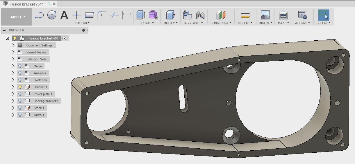
And this is the CAD model I'm hoping to reproduce:
Same part from the bottom:

And corresponding CAD model view:

- 50mm indexable face mill.
- 10mm long series 3-flute carbide end mill for loominum
- 6mm HSS 2-flute end mill
- 12.7mm 2-flute carbide 90 degree chamfer mill
- Drill 2.5mm, 3.3mm. 5.1mm and 10mm


Here's the setup sheet as it stands today:


- I've set up most of the tools and toolholders in the tool library but I need to revisit (and likely reduce) the speeds and feeds for the tools, particularly the 10mm long series carbide end mill. It's designed for aluminium but I suspect it's also intended for use in a modern machine. As I've initially based my feeds and speeds on the manufacturer's recommended settings, they may be a bit ambitious for my elderly beast and my rubber underpants.
- Will probably renumber the tools.
- May mount the 10mm drill in a milling cutter holder instead of a keyless chuck to reduce the total stickout. Besides, I only have 3 chucks for 4 drills and I have a spare 10mm holder.
- Need to set up the tool offsets etc in the CNC controller.
- Cut up some stock (4" x 1.5") ready for getting stuck in.
- Perhaps try out some heavy cuts on some loominum in the vise with the 10mm carbide tool that will be doing most of the heavy work? Can I be arsed?


No comments:
Post a Comment