Even dumber when you bear in mind that I already had several roughing tools mounted and ready to go. I've got a couple of 20mm YG-1 GB753 HSS Co fine roughers that are said to be "good" for aluminium, even if they are actually "recommended" for steel due to the surface coating. The recommended feeds and speeds are pretty decent but I decided to dial them back a bit for now. This is the tool I used to rough out The Startled Man tool setting fixture in steel and it worked nicely, even though I had no coolant at the time.
But even better than this is a 3/4" HSS aluminium hogger tool I acquired in Canada. I expect it's Chinese in origin but either way there is no information about manufacturer, composition, feeds and speeds etc on the packaging. However, I populated the tool library with typical data for HSS machining of loominum. I've only got one example of this tool, so if it goes tits up, I'll have to change to another type eg the YG-1 roughers.
It's pretty quick and easy to set up a tool in the Fusion 360 tool library and call it up in CAM. So regenerating the roughing operations for the 2 circular cavities and the external taper profile with this rougher took no great effort.
To get the tool length offset correct, I took a bit of a shortcut by carefully measuring an existing (chamfer) tool gauge length (actually measured from the back surface of the flange next to the spindle nose) and then entering a calculated figure for the rougher manually into the tool table in the machine. That worked well enough, not least as these operations are mostly side cutting.
I then used the 10mm carbide end mill to complete the final 2D profile for the cavities and outer profile. I suspect that my 0.5mm "stock to leave" may have been a bit excessive, judging by the quantity of fine swarf generated. Perhaps 0.2mm or less would be better.
Small cavity:

Big cavity:


External profile:

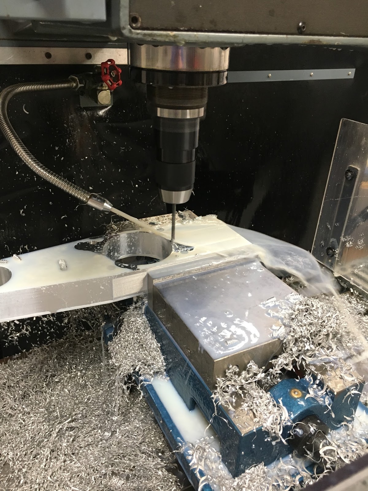
Not looking too bad after roughing:

Then finish off with (one of the 2 remaining) 10mm carbide end mill:


Mill the 8mm slot with 6mm slot drill:

Things were now on a roll. Out came the drills - 10mm:


5.5mm:
....and 3.5mm:

and finally the chamfer mill:
Final result:

Incredible. Job done, no breakages. Looks half decent.
Observations:
- The bore diameters were about 0.25mm undersize. Yet the cutter is bang on 10mm. Not sure what this was caused by - possibly I should have opted to select a final "spring" pass (I think there's a check box for that). I need to look into this...
- The edge of the chamfers had a slight burr thrown up. I suspect the feedrate is too low, so I'm almost rubbing rather than cutting.
- As noted, chip recutting is a problem when ramping into material or opening out a closed cavity. So in a piece like this one, it would make sense to put a hole through the stock with a large drill before starting to mill. Then there would be somewhere for the chips to drain away.
- The coolant system needs to be improved. If possible, I'd like the chips to be blown clear, although this is a messy, wet business. It probably requires some shower curtains as well as a better nozzle system.
Now to turn the work upside down and prepare for the final 8 operations....


No comments:
Post a Comment