I dug out the brake linkage for the Bantam this evening. My
machine was missing this when it was bought years ago (22?). I finally managed to get one from a machine that Bede Tools
(Newcastle) were breaking. It’s 90% there, although missing a couple of parts
like a bronze bush, a simple bracket and a couple of screws. Naturally, the
screws are all UNC thread of which I have none. I’ll end up drilling them out and
retapping metric which will require removing the motor for access etc. On the
upside, the brake pad / shoe thing is totally unused, so should have some life
in it. There is a microswitch on the machine that kills the motor when you
stand on the foot bar at the front. I can wire that into the VFD.
This is what came in the bag of bits. There's a foot operated bar that sits a couple of inches above ground level. This has a connecting rod up to a horizontal linkage (a shaft) that takes the movement over to the left of the machine, inside the change gear housing. Finally, there's a push rod that pushes a friction pad into the vee of the driven pulley. The push rod also operates a microswitch to open the motor contactor to kill the motor when you operate the brake.
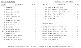
I have the manuals and parts lists for this machine and this is what it is supposed to look like:
The parts list gives the names etc for the compts. Obviously I made up my own names before bothering to check the parts list.
There are a few small parts missing:
There is only one bronze bush on the cross linkage shaft. Easy enough to make up and luckily I have some suitable bar stock:
Done - shaft now has 2 bushes:
Fits nicely. I tapped the end of the spindle M6 so that I can fit a bolt and washer to contain the brake shoe assembly.
The fixings in the machine are two 5/16" UNC threads, 1.5" apart. I'll have to drill and tap those holes in Metric as I have nothing suitable. 5/16" UNC is about 8mm OD, so I could go up to M10. So these holes in the bracket need to be M10 clear eg 11mm or so. I'll whip the motor off and tap the holes before drilling the clearance holes in the bracket. The Blidgeport is ready to go, once I've figured out what hole size to drill....
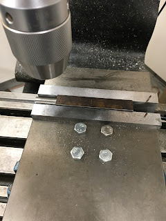
Drilled out the holes 9.0mm:
Hand tapped them M10. Normally I'd use a cordless driver for this but I had an attack of the girly blouse and did it by hand, lest it snapped off. They are pretty shallow holes.
Then drilled out the pivot bracket thing to 11.0mm which gives a nice rattling fit so I can shift it about a little if necessary.
Couple of M10 bolts cut down to size and a coupleof spring washers:
There - seems to fit nicely:
This is the combined gear cover safety switch and brake switch assembly. The cover switch disables the motor if the geartrain cover is removed and the brake switch kills the motor when you push down on the foot bar. They've been disabled since I removed the original 2-speed motor and junked all the original electrics. The cable goes nowhere.
Removed the switch. It's all saturated in oil.
The 2 Bulgin microswitches are identical. They still seem to work OK.
I've rewired it with some 2-core wire and refitted it. Also blammed the original bronze bush into its hole. It was tight - perhaps the extra layers of paint or perhaps the braking system was never fitted in the first place? I don't know if it was always fitted.
Ready to put the rest of the components back together. This shows the link arm that is pinned to the linkage shaft. It was a complete arsehole to get the roll pin back in the hole and through the shaft:
The push rod finally in place, with the adjustable stop for the switch. This was also a complete arsehole to assemble. I had to almost completely dismantle it to get the rod through the hole and the various connections onto their friends:
It extends down through the drip tray onto the other linkage arm. Here's where you adjust the position of the shoe relative to the foot pedal thing.
View from the front of the machine. And yes, this was also a complete arsehole to assemble, too. The return springs are very stiff and are held by threaded pegs. Anyway, here it is finally. TFFT.
I've run the wire up to the VFD but haven't got round to connecting it in to the enable circuit. Shouldn't be a big job.
Next day - sorted. The interlock switches simply wire in series with the normally closed (NC) e-stop circuit. The VFD setup needs to be changed so that the motor spins down rather than decelerates at a defined rate, which is the default. That allows the foot pedal brake thing to bring the spindle to a rapid stop - or the machine to coast down in its own time, depending if you stop it using the pendant or the foot pedal.
On the ancient Xtravert VFD (from PDL Electronics down in NZ), that requires setting the S2 (stop) parameter to "2" (spin stop). First you have to enable config mode by setting Z1 to Y(es) to enable parameter changes, then back to N(o) afterwards, to protect against accidental parameter changes.


No comments:
Post a Comment