Some time ago I overhauled the rotary table / stepper motor assembly that I acquired from John Stevenson. This was originally used by him on his Beaver CNC milling machine. It came without any driver electronics and a rather unusual (to me) plug.
It's an 8-wire stepper motor the size of a large car starter motor(!!), hence the cryptic title. Nothing unusual about an 8-wire motor - it's just a 2-phase stepper motor where each of the pair of phase windings can be connected in parallel or series, according to the application. When connected in series, the back EMF will be larger, so there will be a limitation on the max speed. On the other hand, if you parallel the windings, you will need a driver with a higher current capability.


No idea what the spec is for this machine, as there is no plate on it, nor any other indication of its parentage and parameters. Unfortunately, John is no longer with us, so there's not much chance of getting the info from him. So I'll just have to wire it up and see if it is happy to work.
I have had the Leadshine DM556 stepper driver on the proverbial shelf since mid November, awaiting this moment. I'm not certain (or convinced) that it's a genuine Leadshine product but perhaps that doesn't matter if it works. It cost me less than half the price of the pukka item from official sources. A fool and his money?? Time will tell....
First - need to identify the connections. Various ways to do this:
- Spin the motor with 2 of the windings connected in series. Do this for all possible combinations (4 x 3 x 2 permutations on the face of it) and figure out which windings are in the correct phase:
- Windings from the same phase will either result in double the voltage of each single winding - or zero if they are anti-phase.
- Windings from different phases will add or subtract to result in a greater or lesser voltage than that of a single winding.
- A bit of a PITA this method.....
- Use the scope to directly display the amplitude and phase of 2 windings side by side. That's much quicker and simpler if you have a scope to hand.
- ...and I'm sure you could just use trial and error if you don't mind the risk of popping the driver.
I used the second method. Reasonably quick and simple. In these pics, the yellow is the randomly chosen "reference" (A) winding and the blue windings are the focus of enquiry. In the top pic, the blue winding is out of phase by 90 degrees, so clearly belongs to the other (B) phase.

This winding also belongs to the B phase but is inverted relative to the first picture. So I've identified both of the B phase windings and their correct phasing.

Similar, simple process to identify the correct phasing for the remaining (A) phase. Job done.
Rewire the connector.
Bit of a gamble this, as I'm assuming the motor will prove to be suitable. If not, the next hour or so of rewiring the connector will be a waste of time.....
Bit of a gamble this, as I'm assuming the motor will prove to be suitable. If not, the next hour or so of rewiring the connector will be a waste of time.....
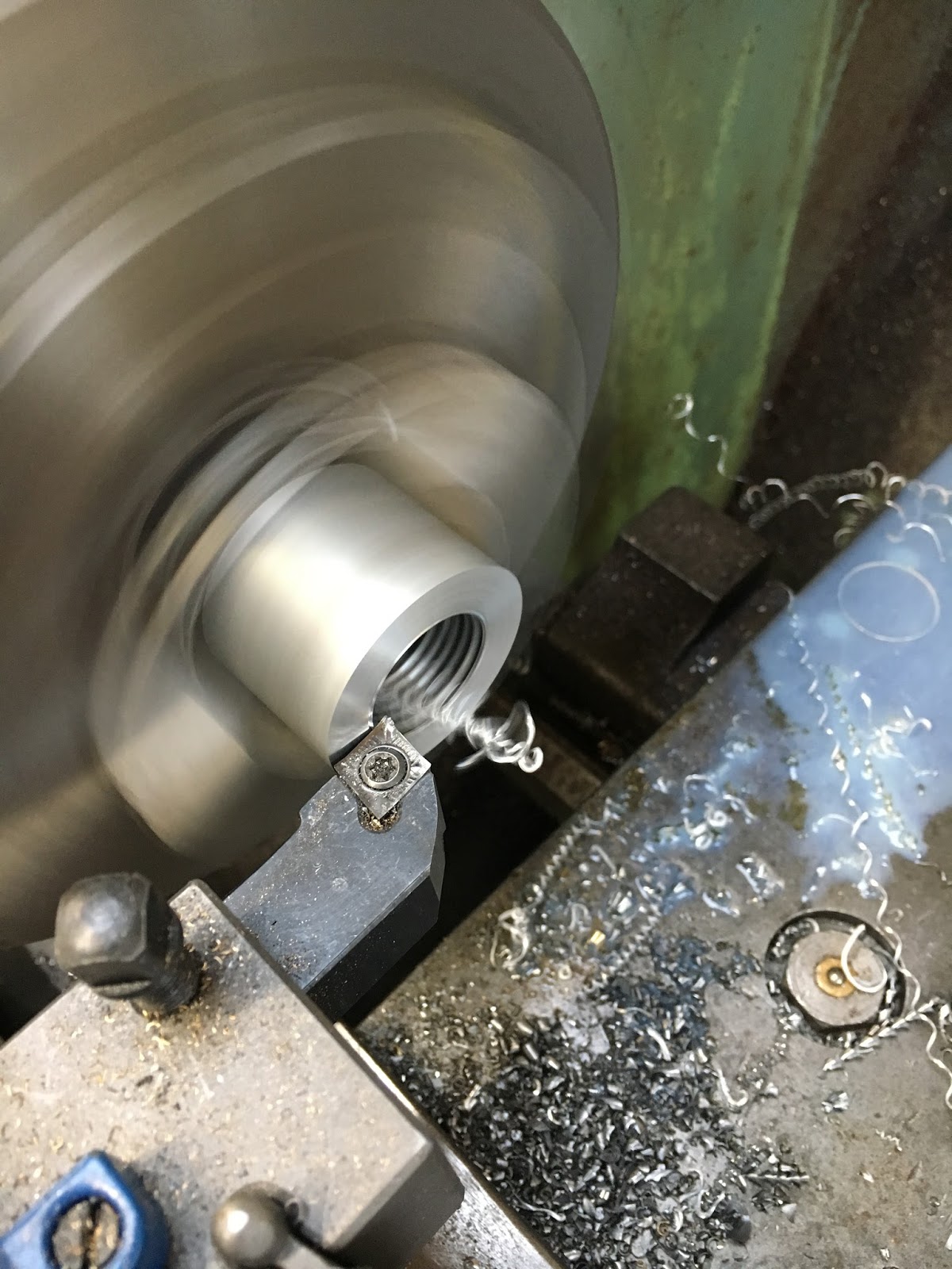
I recovered a decent quality miltary round connector plug and socket from the original cabinet. Spent 20 mins or so removing the old wires and cleaning up the solder buckets on the rears of the inserts. Swapped the pins and sockets around so that the motor side has pins in a cable plug and the driver side has sockets in the panel mount housing. If it goes well, I'll mount the driver in a box and this panel connector on the driver box.
Bodged the loominum adaptor that came with the original connector so it fits the cable conduit on this motor. What could possibly go wrong?


Wire up the Leadshine DM556 driver:
Wired up the motor to the driver using some flying leads for now. And brought out the step and direction signals from the controller through some Cat5 cable. 30V / 5A bench power supply and Bob's your aunty:


Bugger. Works OK unless you actually try to turn it at a vaguely sensible speed. Or turn the micro steps down to zero or close. Although I've got the driver turned up to its maximum 5.6A peak current, I clearly haven't got enough current to drive this massive beast. Tits and piss. So I was wasting my time with the connector.
Back to the drawing board internet:
NEMA 34 stepper motor from Zapp Automation. Not used these boys before but if I by from China it will be weeks before I see anything. It's Chinese anyway, and the price doesn't seem silly. The plan is that a NEMA34 motor flange will be big enough for me to be able to bodge it on to the existing bracket. If necessary I could possible turn down the flange on the motor to suit the hole in the bracket....
Matching 19t "L" sized Taper Lock pulley from Beltingonline.com and "1108" sized Taper lock insert to suit (12mm shaft bore).
The original belt is arguably 3 teeth too long, so increasing the motor pulley size from 16t to 19t should do the trick. I hope. The belts only come in increments of 10t from this supplier, so I can't simply order a belt that is 3t shorter, which might have been simpler and result in less loss of torque.

Controller setup parameters for the A axis:
I didn't try anything too clever in terms of setting up the parameters on the controller for the 4th axis when I was trying the motor out. But now that I seem to have some time on my hands while the new stuff arrives, I may as well figure out the numbers.
First of all - what units are usually used to specify 4th axis movement? Degrees presumably? I'll check with the Smit book later but it is almost certainly so.
Overall stepper > table ratio calcs:
- 120:1 ratio on rotary table
- 19:24 toothed pulleys
- 200:1 basic pulses / rev for stepper (assuming no microsteps initially)
- 360 degrees per rev
So:
Overall ratio is (200 x 120 x 24) / (19 x 360) = 1600 / 19 pulses per degree (approx 84). Can resolve about 0.05 degrees without microstepping.
Sanity check:
1 degree output requires 120 degrees of input shaft (1/3 turn). That is about 151.6 degrees at the motor. This requires 200 * 151.6 /360 pulses ie about 84 pulses >>> OK (sounds correct).
So the parameters for the controller will presumably involve 1600 and 19 as the "numerator" and "denominator" values. You can't enter decimals, so this arrangement is a simple way to enter real world ratios.
So the parameters for the controller will presumably involve 1600 and 19 as the "numerator" and "denominator" values. You can't enter decimals, so this arrangement is a simple way to enter real world ratios.


No comments:
Post a Comment