The servos and spindle motor won't arrive for another couple of weeks and there's plenty left to do besides the axis and spindle drives. I have a fair idea how the turret works but I'll need to fully sus it out and also rebuild it anyway. The exploded parts list gives an idea what's in there but it's almost impossible to figure out the correct sequence to follow for disassembly.
Sod it, let's dive in here. I know somebody's been in here before because there's a homemade tool for removing the castellated nut in the centre of the turret. So let's start here.
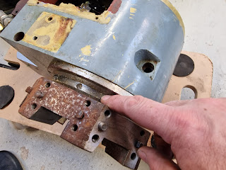
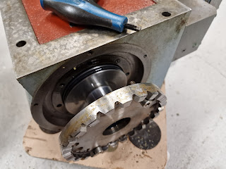
With the turret removed, we can see the indexing scheme. The rear of the turret has a "locating plate" with 6 features that mate with....
18 features on the stationery "index plate". Due to the additional action of the pins on the locator plate, it only actually mates in 6 positions.
The plate is held in place with 4 screws and 3 dowel pins. Luckily there are also threaded extraction holes for jacking the plate away from the turret body.
The cylindrical component provides a surface for a sealing o-ring to work against. It's simply held in place with 4 screws.
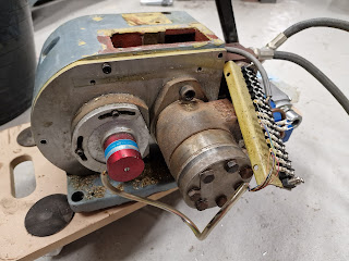
Around the back of the mechanism, there's the hydraulic motor and a 6 position rotary switch. That needs to come off for safe keeping. There are also a couple of wires from the microswitch that indicates when the turret is locked in position.
The locking pawl is activated by a hydraulic piston.
There's a roller thrust bearing here.
The index plate is held by 4 screws.
Again, there are threaded holes for extraction.
Here is the pawl mechanism.
That's pretty much it. Now what have we found?
The static seal between the index plate and the main housing has been shredded. This must have happened last time it was reassembled. That doesn't inspire confidence, so I'll need to carefully examine the rest of the seals.
This is the piston seal. Looks fine, thankfully. And the bore seals in the main housing and index plate look fine, too. So I will need to replace the shredded o-ring but none of the others from what I can see.
Here are my measurements:


No comments:
Post a Comment