The new, smaller (10t) pulleys arrived today, as did the Chinesium ballscrew.
The ballscrew:
...was skilfully wrapped, in the traditional Chinese fashion.

It's supplied with the default machined ends, which are intended for the standard ballscrew bearing bracket things. Arguably it would be helpful to incorporate this into my design without needing any further mods - or as few as possible. The main feature that is missing is some form of keyway for positive location of the pulley. Having said that, I plan to use a grub screw to lock the driven pulley to the ballscrew, so I may get away with machining a flat.

I said keep it simple, fatty!
I seem to be forgetting that I'm trying to keep this as simple as possible. I found previously that the quill stops some way before the yoke gets to the lower casting feature. I may as well make the height of the yoke 10mm shorter and mount the ballnut in its natural form (ie as it arrives, without needing any machining), with its flange outside of the yoke. Then, despite the additional height of the fixing bolts (6-8mm), there is no impact on the travel and considerably less ballache involved in making the components up.
Something like this - 30mm height, giving ~48mm overall height, including some lock washers. The relief channels are 3.2mm, to allow a 3mm ball end mill through. May not be essential but it seems good practice to avoid sharp edges (stress concentrators).
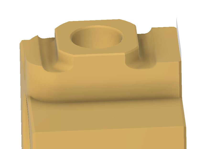
What's with the complicated mating feature?
Why the complicated mating feature?? Well, I actually consider this one of the "strengths" (sorry!) of my design, since a strong and rigid connection between the ballnut and the quill is critical - and this is the main area where most existing solutions seem to be rather weak, literally. The systems such as Elrod and Southwestern Industries have a bit cantilever / overhang due to the position of the ballscrew away from the quill. And BMS250's yoke doesn't seem to have much contact with the quill. My widely spaced contact areas give a much reduced tension on the connecting bolt and a more rigid overall connection. To my mind, anyway.
I could finish machine most of these features from above (as oriented above) with a single ball end mill, once the basic steps have been roughed out. Although a ball end mill won't give as smooth a surface finish on the large radius surface as the side of an end mill would, I'm sure I could make it good enough.
And, yes, I have got rid of the pinch bolts and pinch slot....
Pulley keying:
I also specified the smallest pulley I thought I could get away with. These are the "XL" (imperial) system, with a 3/16" tooth pitch, so a 10t example has a 1/2" root(?) diameter. The motor spindle is 8mm, so that only leaves about 2mm of metal to fit a grub screw to. It's looking as if I may need to either glue it on with Loctite or think of some other form of fixing.
Possible solution might be a pin key (around 2-3mm dia) parallel to the axis, if I place a drilled hole for it carefully before boring the pulley for the 8mm dia motor spindle - then use a ball end mill on the motor shaft. The pin key would slide in between the pulley and motor shaft. Finally, drill and tap a hole (M4?) in the end of the motor spindle to hold things in place.


No comments:
Post a Comment