Having put the Korloy face mill away while I await new inserts, the best means of facing off the stock for the new yoke is using the side of a long series end mill. I can't abide the finish you get using the end face of an end mill and of course it wears out the corners of the flutes like no business. The stock is 30mm high, so a std length cutter won't work.
This is a YG-1 ESH516 "super hardened HSS" cutter and sure enough, it cuts the finest swarf. This thing only costs a tenner and although it may not be able to shift swarf as quickly as carbide, it's pretty good. I have a few of the YG-1 EMC85 extended, necked carbide cutters but using them in manual mode to rough out stock seems a bit daft, not least as they cost about £50 each.
Using a 10mm cutter, 1100rpm, 1mm stepover, full depth (30mm) hardly seems to be pushing things. However, with 3xD cut (I'm impatient), it's prone to chatter of course.


Ready to do the CNC bit now....
CAM for new yoke:
Took a bit of buggerage trying to find a toolpath to create the filleted channels. They might seem a bit odd or possibly even unnecessary but ironically the reason for putting them there is to make the part machinable. Que? Well, the central stub is a cylindrical section that plugs into a mating radial bore on the side of the quill. And the lands at either side have the same radius as the outer cylindrical surface of said quill. It's pretty tricky creating those 2 cylindrical features at 90 degrees to each other but they are what I feel gives this concept
The problem is that I have modelled a 1.6mm fillet and aim to machine the fillet with a....1.6mm radius tool. That just doesn't seem to compute with Fusion 360, even with all the "stock to leave" etc options unticked. I even went into the model and increased the fillet to give it something to work against.

The solution was a bit of a fiddle. I went into the model and deleted all the fillets around these features. Then called up a 1/8" ball end mill and programmed the CAM as if it were a square ended cutter. The end result is what I originally modelled.

Here's the stock model (a simple cuboid). I chose to put the origin where the bolt axis meets the stock surface. The stock surface is now the model surface and the position in X and Y is possibly going to be more accurate if placed midway between the vertical faces than if I use a corner of the stock.
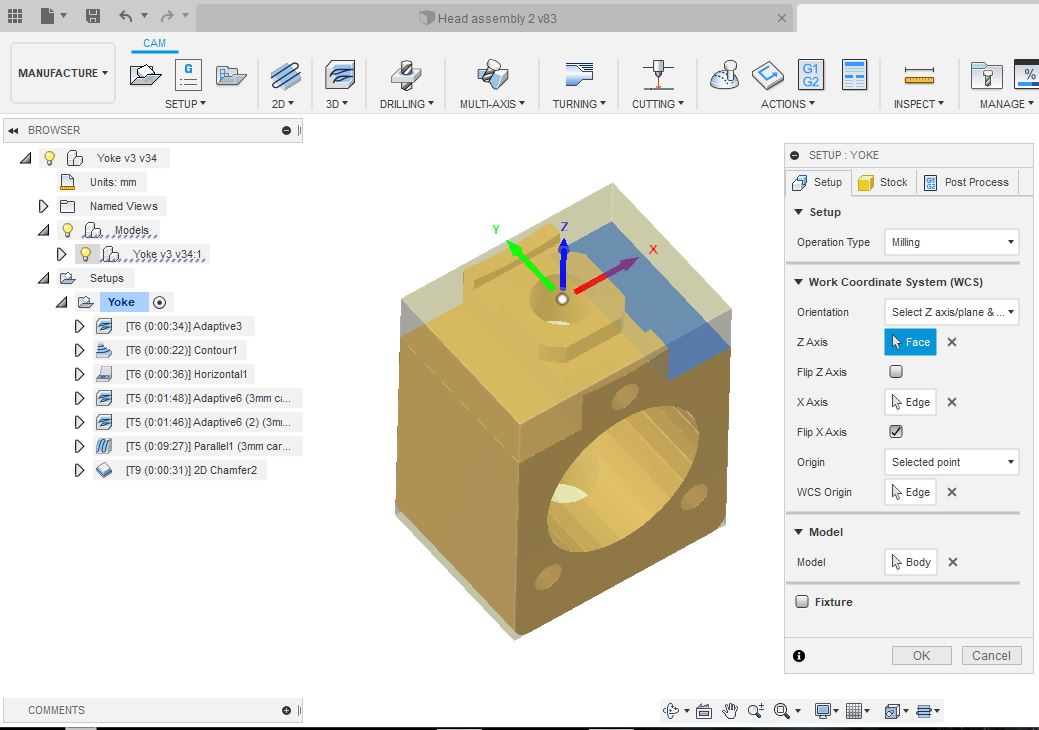
The stock model coincides with the CAD model quite convincingly.

Making swarf:
Here's the ball end mill roughing out the fillet slots either side of the fixing boss.
That went well.

Finally, I drilled the fixing hole manually (with the MPG), as the Z axis movement wasn't enough to accommodate the long drills.


Happy with that. And it's a nice snug fit in the quill. The whole thing took about 15 minutes to machine.

What's next?
To finish this off, I need to counterbore the fixing hole and drill / tap the three M6 fixings that hold the ballnut into the yoke. Then I'm done.


No comments:
Post a Comment