Don't bugger about, fatty. Chopped up the stock, loaded it into the vise, lined up the tools, checked the tool length offsets (reset them), then kicked off. What could possibly go wrong?
Well firstly I broke my first ever Renishaw probe. No, not doing anything meaningful - quite the opposite. I was just coiling up the cable to avoid it getting caught in the moving parts. The cable caught the probe tip and PING. I hardly even noticed it, although I caught sight of something fucking off across the table. Shit. Lucky I bought those Chinesium clones off Aliexpress. So now I'm down to the last 2 (only ever had 3). And now I need to dial the replacement tip in before I can use the probe again.
Then I must have forgotten to save the Zref measurement when I set up the stock. I thought this was saved when the Zref operation was done but it seems not. You live and you learn. I was saying the other day that I'm not 100% clear what happens. That and getting a bit doddery. Yep, the wheels are coming off....
The first move of the first operation is to start the spindle at 3000rpm and plunge down to retract height. Given that the table has risen by 30mm or so, this was never going to end well. Having said that, the end mill survived(!) by being pushed into the toolholder. I stopped the machine before anything significant happened. One of the teeth has a slight chip now but nothing bad enough to require a new tool. Reset the tool and remeasured the tool length etc. Then off we go, this time with less drama. Luckily the machine coords didn't get messed up in the crash, as the only move was a vertical one.
So having pinged one Renishaw probe and almost nadgered a carbide end mill straight out of the trap, I seem to be doing well before I've even got going properly.....
Finally doing some machining:
Well that seemed to go OK.


Hold up a minute...
But wait a minute. The register is supposed to be 0.3mm oversize in radial stock to leave yet it measures 94.5mm instead of nominal 95mm. And with the stock to leave it should be 95.6mm. I know Adaptive toolpaths are rough but that's taking the piss. Something funny(?) is going on here!

Sure enough, though, when you look at the simulation, it predicts that the part will be undersized after the 2D Adaptive operation.


Software generally doesn't have a mind of its own, so the explanation is likely to lie between my ears - if only I could find it.
In fact I found I needed to leave at least 0.6mm before it will be big enough to actually leave any stock. It's a good thing I left some extra radial stock for the lathe finishing, otherwise I'd be undersized. Oh, wait a minute...
At least the external diameter is OK. For this one I used the 2D Contour operation with 0.8mm stock to leave, coming out around 126.6mm (cf 125mm final dimension in the model). I should be grateful for that I suppose.

So I didn't see that one coming. Looks like time to cut another piece of stock and get cutting again - once I've figured out WTF is going on.
The explanation:
Seems I must have programmed the CAM and set the geometry before I deleted the chamfer feature. I say that because there's nothing anywhere at that location / diameter that I can pick up now. Clearly I'd managed to pick up the chamfered edge rather than the full diameter. And as it was a 0.5mm chamfer (from memory), I needed to set the stock to leave to a greater value just to avoid cutting undersize.
So I created a circle from the projected profile and used that to define the geometry.
Rinse and repeat:
At least most of the g-code files have been created and proven already. So once I'd recreated the 2D Adaptive toolpath, I was off again. The whole thing took about 40 minutes to set up and complete. The counterboring of the 12 fixing holes dominates the total machining time by far. Can't help thinking it could have been sped up a lot but hey.

That's better - ~0.5mm radial stock to leave (~1.0mm on diameter):

Set free and cleaned up with belt sander and Noga deburring tool:

Now for the other side: Now machine the register that mates with the harmonic drive:

Good - nice fit, no cockups:

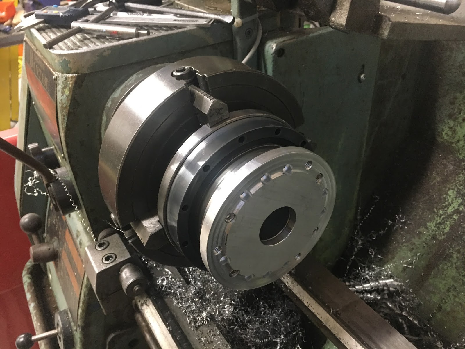
Next, get the harmonic drive set up nice and true in the 4-jaw. Ended up about 10-15um runout, which is better than the 3-jaw will manage by quite a way. Happy with that:

Now mount the backplate and prepare to machine the register for the chuck in situ. Ideally I will remember to mark the backplate and drive face before dismantling them, so that I can reassemble at the same angular alignment at a later date. May not make much difference but it's good practice.

Nice tight fit. Stays on without fixings...

Chamfered and ready to come off


There.


No comments:
Post a Comment