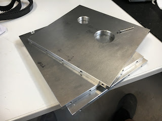
First, chop up the 700 x 305mm x 9.5mm plate I've had kicking around for the last 20 years or so. The Evolution mitre saw does the trick, although it's not suited to plunge cutting into the material. Requires a slightly different technique until the slot is started....
...then you are off.
Makes an unholy mess but at least there's no grit involved, unlike with an abrasive cutoff saw.
This plate is at least 20 years old to my certain knowledge. The problem there is that the polythene(?) covering has perished and is a sod to get off. Nothing easy here. Being impermeable, there's no benefit in soaking with IPA or WD40.
And finally we're off:
Counterboring
Quite a bit of stickout from the vise
Tapping M4 with the tension compression head
Side plates done
Close resemblance!
The rear plate has a hole for the control cable (conduit) as well as the hole for long stock to poke through.
The Renishaw probe was essential here.
Yes, this is a broken 3.3mm drill - on the 3rd last hole of the job. It's the closest to a cockup in the entire process, presumably due to swarf clogging within the hole. I was pecking at 5mm steps with full withdrawal - but that doesn't ensure the swarf doesn't stick, even with flood coolant. Aluminium-specific drills might possibly help but I don't have any. Still, there's enough meat to tap to a 10mm or so depth as it turns out:


No comments:
Post a Comment