Saturday, 29 April 2017

Install drawbar controller

Now that I appeared to have sussed out what it does and how to connect it up, it was time to install it on the machine for real. As discussed, I intended to use one of the quill top switches and one of the (two) VFD digital outputs configured with the "spindle stopped" function. This is normally open, open collector (rated at 48V / 50mA), so should be fine with 24V and the input of a solid state relay (SSR). The SSR will switch the AC power to the whole drawbar controller. 

That leaves the "tool in" and "tool out" functions. I actually need a direction signal (clockwise or counterclockwise) and an enable signal. So in fact, a push to close switch with 2 switch elements will enable the impact driver and reverse its direction and a simple push to close switch will enable the driver in the forward direction.


I have a load of old switches from the front panel of the original console. I don't normally scavenge 30 year old switch gear on the off chance of using it at some point in the future. However, there were some switches that had almost certainly seen very little use (A-axis jogging for instance) and I didn't have anything better to hand. Furthermore, they would fit nicely in the existing box, as would the SSR. 


I also had a few cable glands and conduit to reuse. But it meant a whole load of rewiring, soldering, crimping, drilling, tapping, cable pulling etc etc. For one thing, there needed to be a 240V supply from the control box or VFD to power the controller and a cable to bring the interlock signal from the VFD via the quill switch to the controller. And the impact driver and solenoid wiring up the the top of the head.


I will fit new labels but this is what the new controls will look like. The lettering is actually engraved, so I can't simply rub it off.
 Deburring a large hole on the inside of a steel box is often quite tricky, especially when you haven't yet found where you packed the deburring tool. This countersink tool can actually be used backwards, especially if you reverse the drill direction! It wasn't intended for use like this but proved a handy technique.
 This is a trial fit of the switches. I decided to move the PCB down and to the left a bit later on, to clear the switches and make room for the SSR - you can see that in the following 2 photos. The dual switch is the one at the top - it's a modular switch system. Although they are marked "RS", they are uncharacteristically not marked with an RS part number. The front bezels, symbols etc are removable and can be customised but I'm happy with the simple up and down arrows from the original jog buttons.


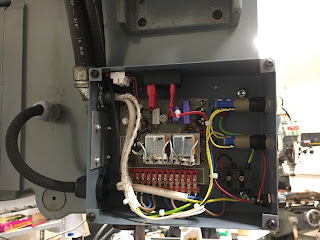
 This is it half finished. I later moved the outputs to another hole nearer the top to make room for the mains and interlock signal at the bottom. As you can see, the PCB has moved itself down and left.
It seemed rude and possibly ill-advised to perch the drawbar mechanism back on the top of the machine without taking it apart for inspection, cleaning and relubrication. It's fairly simple as you'd expect. It looks rather like the Kurt and Align drawbar engagement solenoids that are widely used on US Bridgeport-type machines fitted with the R8 collet system. And of course, the impact driver solution applies generally to manual machines - automatic machines tend to have pullstud toolchangers.


There's not much to go wrong apart from the o-rings. They looked fine. The splined drive parts looked to be in fairly good condition, so after a clean up, reassembly and oiling, it all went back on the top of the machine, rather like a noisy fairy on a Xmas tree.


The whole thing is hidden by a large cylindrical sheet metal cover, lined with noise deadening foam. That will go on (much) later when I have finally finished with this part of the system.

Then back to installing and wiring up the drawbar controller itself. This is the wiring on the VFD. "P1" is the 1st of the 2 Programmable digital outputs (they are simple opto outputs). The "PC" terminal is the digital common (ground) which is connected to the CNC system ground, along with the analogue ground and digital inputs ground. So when the P1 open collector output goes active low, the -ve input of the SSR will be pulled low via the (hopefully closed) quill top switch. With the +ve input of the SSR connected to 24V, the solenoid and impact driver should come to life when I press either of the push buttons - but only if the conditions are safe.
I also installed my Class D bluetooth audio amp and Eltek cabinet speakers in the workshop. They make a hell of a difference. Got myself a bit of Eric, some Robert Cray, Erasure and Steely Dan going on for starters. I can crank it up as far as I like and it doesn't disturb anyone.

The musical bluetooth activity killed the battery in the iPhone, so more pictures will have to follow later. 


Update - this is what looked like at the end of play yesterday:


Still to do:

  • Configure VFD digital output for zero speed function.
  • Connect 24V supply to signal cable
  • Connect up pneumatic solenoid electrical and air
  • Get it tested
Sunday evening - all done apart from solenoid. Works very nicely. Rapid up until it hits the soft limit, then press the "tool in" or "tool out" button. Doesn't work unless the quill is at top limit and spindle is stationary. Sound.

Friday, 28 April 2017

Power drawbar - controller box thing

I dug out the original power drawbar controller. This is a single-sided PCB in a steel box that was mounted on the side of the ram housing. The impact driver was wired into it, as was the pneumatic solenoid that engages the impact driver with the splined end of the drawbar.

On the board are a couple of 240V relays and a 400V SCR. Apart from the 240V supply / fuse / toggle on-off switch on the supply side plus the aforementioned impact driver and solenoid, the only external connections are 3 wires that used to connect to the contacts of a couple of relays in the old control box. Everything on the PCB is at mains potential, so there will need to be additional relays between the CNC controller and this box if I keep it.


There are 2 primary functions you'd expect from a simple drawbar controller - control of the impact driver direction (including powering it on and off) and activating the solenoid. On a good day you'd also ensure there was a delay between the solenoid engaging and the impact driver starting to turn, to avoid nadgering the splines. On an even better day you'd actually use a microswitch to detect that the driver is actually fully engaged with the splines before powering the driver but that would make things more complex than strictly necessary.


With 3 wires and 2 functions, one of which is connected directly to neutral, it's pretty clear that one of the remaining 2 wires represents "on - off" and the other sets the direction. And the components on the PCB are primarily for a time delay circuit that drives the impact driver through the SCR. I wired up a dual changeover light switch to test it quickly, with the solenoid and driver lashed up. Turns out that the second relay wasn't connected to anything on this system.


Well it worked - but it had to really didn't it? There's not much choice in the matter when you only have 2 inputs and 2 required functions and it was working when last connected apparently.


I reckon I'll just wire it up on the machine for now. I don't have any compressed air so it won't work for now unless I manually engage the driver with the drawbar. But hopefully I will have a fix for that soon. 


Required for final operation: 


  • "Tool in" and "Tool out" push buttons, ideally 240V, to avoid need for yet more relays.
  • Interlock with VFD, perhaps using a "spindle stopped" output to control a (solid state?) relay preventing drawbar operation until the spindle is stopped. 
  • Possibly a means of engaging the electric spindle brake during tool change.
These are the functions you can assign to the 3 multifunction output terminals of the Yaskawa V1000 VFDs:
In particular, the zero speed function would be quite handy:

This could be used to directly drive a SSR that powered the power drawbar circuit - or its enable signal. Then the drawbar could be prevented from trying to operate unless the spindle were stationary. I could further enhance the safety factor by running said signal through a microswitch detecting if the quill was at the top (tool change) position. Then the drawbar will only attempt to operate if the quill is at top of travel AND the spindle is stopped. Given that I have 3 switches at the top of travel (one is currently used for limit, one is used for dead stop), there is one spare that could be used for this purpose. Sounds like a plan, particularly if I fit the (tiny) SSR into the original drawbar controller box...

Thursday, 27 April 2017

Mystery macros

Spent a couple of hours yesterday evening trying to figure out what on earth the "automatic tool setting gauge" macro is supposed to do / how to get it to work.

Here's what I have from the manual:

2.1  Usage for automatic tool setting gauge


1.  Note for parameter:
Define macro variables of the automatical tool setting gauge function are as follows (corresponding to the other parameters P380 - P389):
#380: The X axis lathe coordinate of initial position with automatical tool setting;(Unit:mm)
#381: The Y axis lathe coordinate of initial position with automatical tool setting;(mm)
#382: The Z axis lathe coordinate of initial position and returning point with automatical tool setting;(mm)
#383: The negative speed of automatical tool setting;(mm/min)
#384: The positive speed of automatical tool setting;(mm/min)
#385: The Z axis coordinate of workpiece surface in current workpice coordinate system after automatical tool setting;(mm)
#386: The speed which is rapid move to locating position with automatical tool setting;(mm/min)
#387: Automatic tool setting mode (1 means fixed point, 0 means floating point).
#388: The minimal lathe coordinate value of Z axis (mm);
#389: The gap value of Z axis  [The height which is the gauge surface relative to the workpiece surface(mm)];
Fixed point gauge means putting the gauge in a fixed position, everytime the X Y Z axis are automatical running to the fixed point first in tool setting; But the floating point gauge search the tool setting gauge signal along negative of the Z axis.
The input point X25 is default to be the checking point of automatical tool setting gauge to input.
2. The instruction: M880 (corresponding to ProgramUser0) automatic tool setting instruction; M882 (corresponding to ProgramUser2), M883 (corresponding to ProgramUser3) set the gap of Z axis.
3.  Automatic tool setting steps:
a) Set the No.380--No.388 parameter in other parameter;
b) Set the No.389 parameter in other parameter to set the gap of Z axis: this operation needs to be set only once.
A.Run M882 instruction in MDI to set the gap of Z axis;
B.Manual run Z axis to move the tool nose to the workpiece surface;
C.Run M883 instruction in MDI to automatical set the gap of Z axis No.389 parameter in other parameter;
c)  MDI choose the workpiece coordinate system G54/G59;
d)  Automatic tool setting: MDI running the M880 instruction, automatical set the Z axis offset of the current workpiece coordinate system.

I think I sort of get some of it but it's going to take a fair bit of trial and error to suss it out. Although the controller language is set to (Ch)English(?), when trying out these functions, there are various popup messages that appear that are naturally in Chinese. With the help of Google Translate on my iPhone, it's relatively quick and simple to translate these. There are 2 modes - either "live", using the camera where the Chinese characters are substituted by English words even as you watch the live picture - or slightly less live where you take a photo and the app sends the photo somewhere for scanning and translation. The latter only takes a few seconds and is usually more accurate / more intelligible. 

At various points, I was able to get messages telling me that I had either confused it or that it had successfully acquired a position. But nothing I could usefully apply yet by quite a way.


It seems that there are 3 "macros" involved in this tool setting procedure. I have no idea if it's possible to view or edit (or create) macros, although there is no mention of it anywhere in the manual unless I've missed it.

  • M880: This starts moving the Z axis up to the upper limit, then downwards at a slow rate (presumably one of the parameters #383 or #384). If you then short X25 input to ground (you can check the changing status in the diagnostics screen), it stops and reverses back a short distance. I guess this is the tool hitting a tool setting switch then being withdrawn.
  • M882: Don't understand this. I think I got it to report succcess but it didn't make any moves as such and I didn't see any coordinates being changed.
  • M883: This writes a value to the Z coordinate stored in parameter #389. That seems to be the whole point of this procedure. But I don't get how the value relates to any of the machine, work or tool parameters.
Part of the problem is that the manual has clearly been translated by some form of online translation tool. Google isn't generally available in China, so I assume it is a local equivalent, possibly a Baidu tool. I've asked for the original manual in Chinese so that I can have a go at translating it myself, as I surely can't do any worse. I've also asked for the communication software that is supposed to allow you to connect a PC to the controller over RS-232 or USB. And the missing password that prevents me from backing up the system config.

I suspect I may cut my losses for now and instead just enter tool lengths etc manually into the tool table. I could spend days or weeks failing to even understand what it is supposed to do. There are plenty of other things I could usefully make progress on:
  • Tool changer hardware and setup. Today I received some nuts and olives from Chris Gunn that will allow me to connect up the pneumatics for the drawbar actuator and the spindle gear changer (thanks Chris!!). I also have some 1/4" (not 6mm) hose left over from plumbing in a US-style Samsung fridge about 6 years ago.
  • Tool changer impact driver controller. This came off the old system and seems to use a couple of relays to engage the driver and then power it forwards or backwards. There's also an SCR or triac and some timing components. I think feel an Arduino application coming on - or possibly the PLC function in the controller - as there are several inputs and outputs required to control the sequencing and interlocking of the various components involved, such as the spindle motor, spindle brake, drawbar actuator (solenoid), impact driver, VFD (spindle stopped) etc. Much of that was done in the old controller console and I suspect the above controller circuit probably won't be much use by itself.
  • Spindle gear selection. It's only 2 speeds and I won't need low speed for a while but at some point I may want to try to set up rigid tapping which requires low speeds and high torques as well as an encoder on the spindle. Again, various inputs and interlocks will be required to avoid crunching noises.
  • Chip guard and swarf tray. These need to clear the controller and spindle. I also need some flexible (soft) plastic curtains to act as chip catching curtains. Those heavy transparent clear PVC(?) curtains used in warehouses, commercial display fridges and shop entrances would be ideal. I wonder where to get some? The machine used to have some but clearly the plastic perished so only the metal frames remain.
  • I'd like to know why my MPG doesn't work. Perhaps once (if) I can get my questions answered by Newkye / Newker, I may be able to ask them what on earth is going on with it.
Certainly, the toolchanging (or lack of it) is a royal pain in the arse. So perhaps I should get that cracked first of all. One initial problem is that I don't fully understand how the impact driver works in the tool changing context. What limits the torque apploed to the drawbar / tool? There is a spindle brake (electromagnetic friction from what I can see) but it is part of the motor, so clearly will exert a much higher slipping torque when in low gear. The brake must surely be applied for drawbar tightening / loosening, otherwise the spindle would simply spin and the tool would not be tightened. But what limits the applied torque. It might help if I understood how they work, so that should be the first thing to clear up.

I'm wondering if the spindle brake is worn. I had the bright idea of applying the brake (24Vdc) when loosening / tightening the drawbar manually but found that it slipped before enough torque could be applied. And I wonder if the SCR / triac circuit was a means of controlling the applied torque in the impact driver. Both the commutator and stator connections were taken out to the controller box.

Tuesday, 25 April 2017

Better metal

The scrap of loominum I used yesterday was cut off from  larger piece by hand on the bandsaw a couple of years ago. When I measured it today, the sides were out of parallel by around 0.5mm. Perhaps not surprising it came loose in the vise.

I cut a 25mm piece off a length of 1" x 2" bar, so the sides were somewhat more parallel. I had to alter the model to make it fit in the narrower stock, otherwise I was able to use the same model for attempt #2.

I buggered up my first attempt with the new stock. The feed rate was turned up accidentally and I don't seem to have got the Z axis zeroed correctly. I also found a bit gouged out of the side which I don't understand - rather like a lot of things at the moment!


I double checked the cutting parameters against Sandvik data for the same inserts and did sanity check comparisons against the likes of the Shear Hog and solid carbide cutters. The fact is, you need to run these cutters very hard and they only have one insert. So the racket they make is quite different to (and louder than) the noise you get from an HSS cutter running at (much) lower speeds, often with coolant or lubricant.


I also noticed that I had left the feedrate set to 150%, so even the fairly aggressive setting were being notched up another 50% over what I'd intended. Hmm.


So, with the stepdown reduced to 5mm (over a 15mm depth ie 3 roughing passes), the feed per tooth reduced to 0.05mm (300mm/min at 6000rpm) - and the feed override turned back down to 100% - off I went again. It still flies along, makes a racket and shifts a lot of swarf.


That's better. I used some WD40 to lightly lubricate the cutter, as there were signs of built up edge stuff on the edge of the insert. Here we go:

And the result: 


So that's my first successful bit of metal cut. Total machining time alleged to be around 7 minutes. Chips everywhere - must get round to fitting the guards and swarf tray. There is a bit of a blemish on the side of the "feature" but I have no idea at this stage what caused it. Perhaps later I may have the ability to figure it out.

Monday, 24 April 2017

Metal cutting?

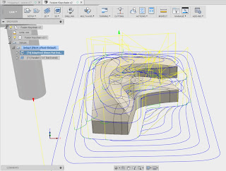
Thought I'd better try something a bit more adventurous than wood for my next trial, so the lads in the armchairs don't have too easy a laugh. So I grabbed the Fusion keychain example from the CAM samples folder and tried to make a toolpath for it. Or rather a roughing operation using a 12mm square ended cutter, followed by a finishing operation using a 3mm (1/8" actually) cutter. The latter is a bit small but it's the only ballnose I've got below 1/2". 

Anyway, I struggled somewhat which perhaps wasn't surprising given all the myriad options and parameters required in the setup screens. I either ended up generating no toolpath at all or something that didn't look at all authorised. 

So I just created a very simple 2D part to begin with. This would allow me to do some nice roughing (2D adaptive) followed by a finishing (2D profile). 

 Roughing:
Finishing:

I have a nice Mitsubishi BAP300 indexable end mill tool (12mm diameter single APMT 1135 insert, 16mm shank) and a selection of coated (for steel) and uncoated (for loominum) inserts. The loominum ones are polished and razor sharp, so should give a good finish as well as cutting the mustard during roughing. Hoho - tools for the job!!


Finally got it all CAMed up and a piece of mystery loominum in the machine vise. Ready to go - what could possibly go wrong? Settings were like this, taken from the Mitsubishi website with additional sums from HSMAdvisor, not least a sanity check that the spindle motor wouldn't be overwhelmed:

  • 5000rpm
  • 0.15mm/tooth
  • 350mm/min
  • 4.8mm optimal load (about 40% of the cutter diameter)
  • 8mm stepdown (on an 11mm insert)
Well, I thought bollocks - go big or go home. After jacking up the Chinese machine vise, the parallels were just about loose enough to remove, so this I did. Perhaps they should have stayed where they were.....

Sod it. I hit the tit and off it went. Didn't sound too bad. The first (roughing) operation is intended to take 2 passes, as the total height of the feature is 16mm, randomly chosen to present a decent load to the cutter.

The second pass started OK - until the workpiece moved a few mm in the vise. It got pushed down into the vise against the non-existent parallels that I'd just removed. Gah! That increased the load somewhat and once the cutter got a little further round the workpiece, the workpiece rode up a few mm the other way. So I stopped. Nothing broken, just a bit pissed off that it had only got half way through the roughing.

The first pass was actually pretty decent looking for a roughing operation. But after the workpiece was pushed into the vise, the tool shank did some friction machining of the edge of the workpiece. 
You can see where the tool ended up further down than had been fully authorised. The other consequence of that was the top of the workpiece  rubbing against the shank, generating a nasty growth:
 But actually, not a bad result up to that point. 


NB: The edges of the second pass are not supposed to be parallel, as it's using a 2D adaptive clearing toolpath. The unauthorised issue resulted in the vertical dimension going to cock.

The Chinese vise has polished and ground jaws, so the coefficient of friction must be in the region of only 0.2 - 0.3 or so. And removing the parallels that would have supported the workpiece probably wasn't the cleverest move. But nobody died and in fact it all went pretty well for a first test. My first ever CNC metal machining.

Luckily I managed to record the beginning and end of the session by turning video off when the machine started and back on afterwards. A senior moment I suppose but at least I didn't screw up the stills....

I'll have another go tomorrow with another piece of loominum - and some parallels. And who knows, I may even succeed in videoing some of it this time.

Arc Captain MIG200!

Yes indeed. Not content with a solitary TIG200PACDC TIG welder , I've gone for the matching pair. ie the MIG200 sister unit. There was ...