Then created a simple 2.5D CAM model, taken from the Fusion 360 CAM examples folder (we all have them in the data panel, I believe) and used the generic Fanuc post processor to generate g code.

Had a few issues trying to load the file into the controller (it's my first time), then compiling it (won't run otherwise). It didn't like the tools that were called up, presumably because I hadn't set up any tools in the tool table. Reselected the tools in Fusion 360 (made them all T2 - a 12mm end mill), to avoid the need for any tool changes, regenerated the g code and then all was good.
Once loaded from the USB stick, you have to compile the code before running it. You can display a crude 3D graphic of the toolpath as the program runs.
Looks good! The movements are all within the soft limits set earlier, which seem to work fairly consistently as far as I can tell. Woohoo!!
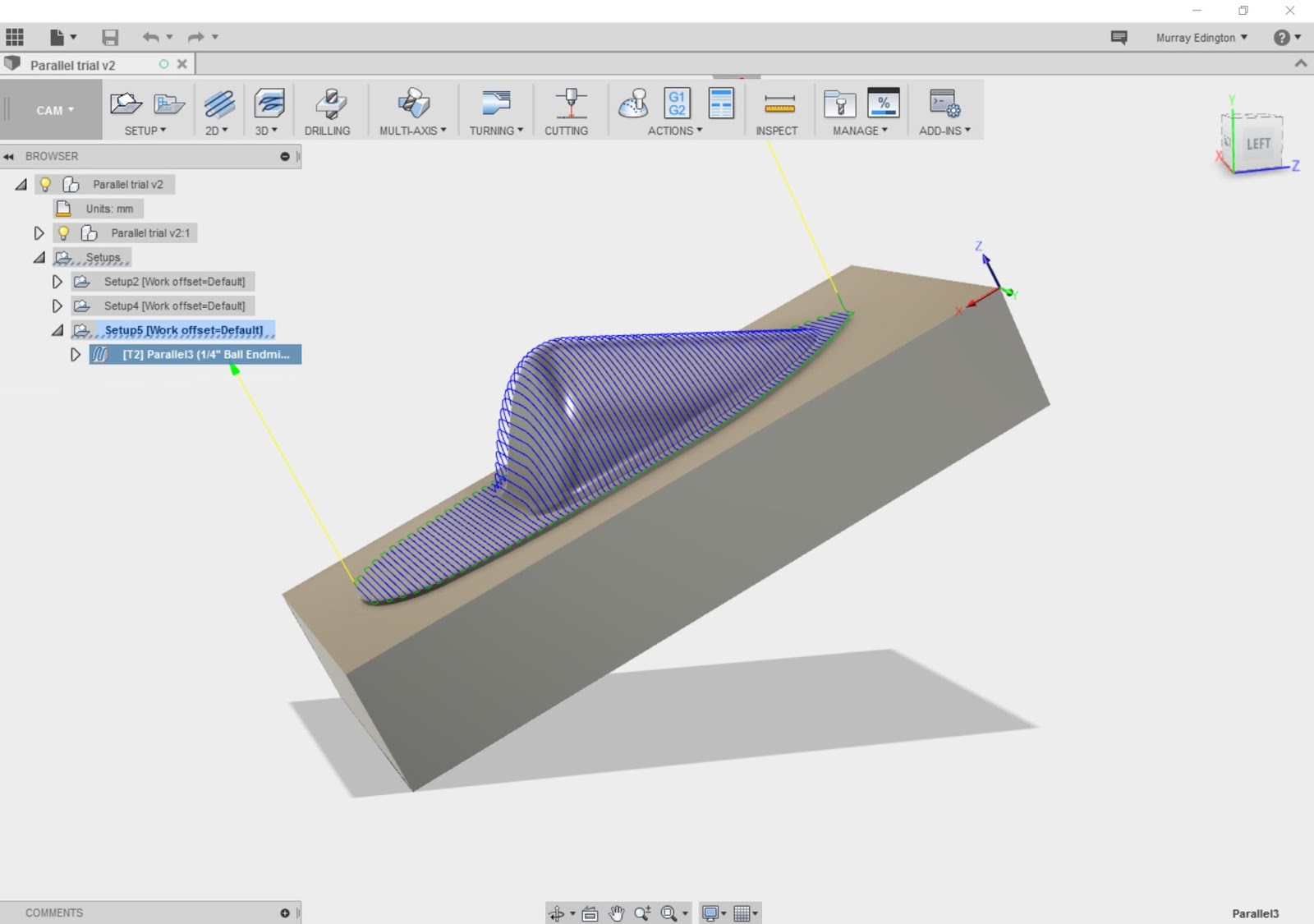
And here's a proper 3D toolpath, using the parallel strategy. Not the most sophisticated toolpath but generates a true 3D output.


No comments:
Post a Comment