Friday 21 April 2017

CAD model for test piece, CAM toolpath and.....first cut!

"Made" a test piece in Fusion model environment, then created a toolpath in the CAM environment, ready for my first ever attempt at CNC machining.

Firstly I created a test piece loosely based on ISO 10791-7. This contains various features that are used to check the accuracy of the machine. There appear to be 3 sizes (80, 160 and 320mm outside length), so I modelled the smallest 80mm  "M1_80" version. I simplified the 4 fixing holes to avoid the need for more than one tool, otherwise it's as close as I can get it, based on the limited information available to me.

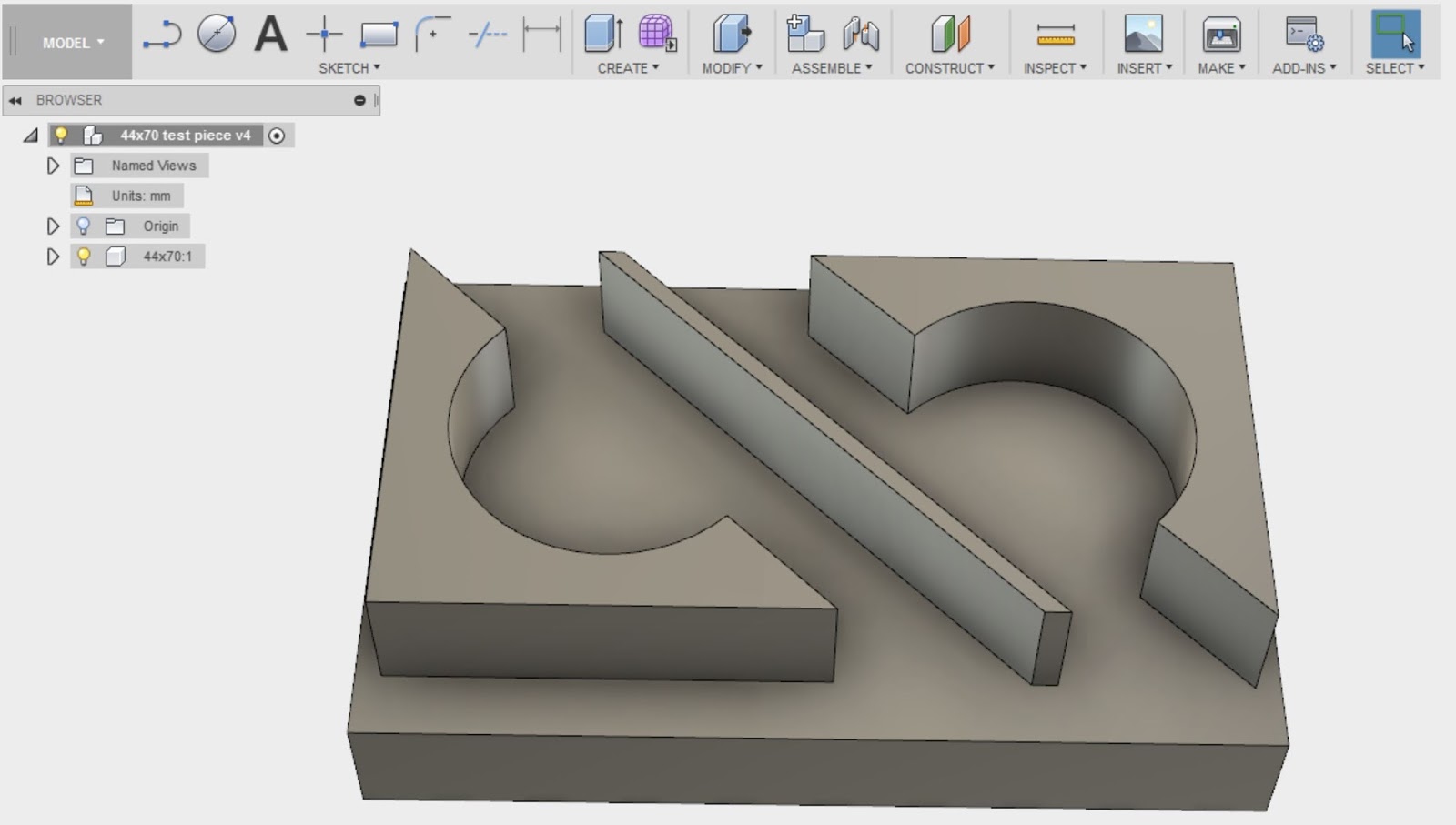
However, I don't have any material that is 80mm square, so I made up my own test piece model that conveniently fits on the end of a piece of 3" x 2" pine.
Then created a toolpath. I had intended to use a 1/2" end mill but that was too big to develop any sensible detail in the model (given the 70mm x 44mm dimensions of the stock), so I ended up changing to a 6mm one. It's the only one I've got, so I'd better be careful with it.
Then post process the toolpath and save to USB flash drive and load onto the machine. Finally, position the tool control point at the top front left corner of the stock and set this as G54, as previously defined in the CAM environment. Then there is nothing left to do but press the green button...

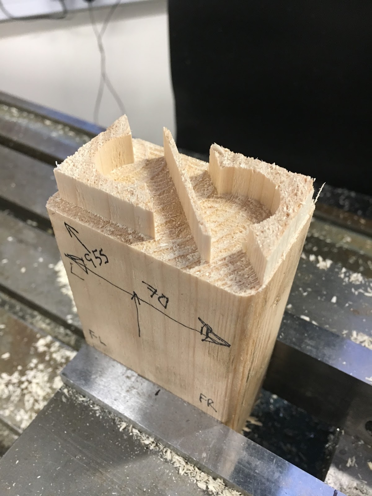
Here's what happened:

And this is the final result: 

I've already apologised for allowing The Brown Stuff to be machined in the workshop but it won't become a habit. Call me a girly poof but it seemed the right thing to do at the time. Must see if I can find some loominum or steel to machine next....

Time for some celebratory beers!

No comments:

Post a Comment

Final assembly and test of the spindle nose adaptor - RESULT!!

After the recent distraction caused by the 3D scanner, resurrecting the 3D printer and buggering about with the throttle bodies for my Honda...