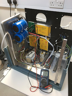
The full DC bus voltage will be around 130-140V but I have only tested one of the drives with a bench supply set to its maximum output of 30V and 10A. Playing around with the gains in the PID tuner software suggested that the stability was in fact fairly close to optimal. That's just good fortune to a fair extent. However, bunging the supply voltage up by a factor of 4 or 5 will reduce the proportional gain margin by the best part of 6-7 dB, so I might find that simply powering the system up could result in some unintended movements in both the machine and my underwear.
Quick tidy up before doing anything else. Here's what we've got as of this morning:
The controls will all work from 110V mains voltage, as the PSUs and time delay relay are all universal input (100-250Vac). So I put a 240-110V site transformer on the input, reducing the internal DC bus to around 60Vdc off load.
Firstly, I thought I'd better check the motor phasing. There's a 50% chance of wiring the motor the correct way round so that it moves in the direction the driver wants it to. Otherwise classically the (closed loop) servo system will send the motor at full speed towards the end of travel in the wrong direction. This CNCdrives diagnostics software is smart enough not to energise the motor until you ask it to, so it's only when you ask it to move the motor by a predefined number of steps that it will let you know if you've got it right. And if the positional error exceeds a definable limit (number of steps ie distance), it will kill the drive. Just as well, as sure enough I'd got the motor the wrong way around.
Swapped the motor wires over and it works very nicely. Sure enough, the stability seems a bit marginal now using the default settings, having increased the loop gain by 6 dB or so - but nothing problematic for now. The main issue is that I have 3 tonnes of machine sitting on a rather "compliant" (springy) wooden home made pallet. I needed this to get the machine into the workshop (pallet truck etc) - and will likely require something similar when the time comes for it to be moved out again. The movements of the machine table are fairly abrupt and indeed I'd like to be able to shift the table around at a decent lick when it's all up and running. But I don't fancy getting squashed by a load of Japanese cast iron. It's been playing on my mind for a while now.
The machine base has 4 height adjusters. I have a load of brick paviors left over from the recent patio extension along the front of the new dining room in the extension, so 8 of these and some steel section did the trick. Ideally I'd make up some solid steel or aluminium feet and then get rid of the pallet but the cost would be not insignificant. Perhaps when the welders are up and running I will make something up from a piece of 2" x 3" heavy section steel beam I have left over.
So I seem to have a working servo system, based on that minimal test. At this stage I don't want to run the machines any more until I have limit switches, e-stops etc wired in, lest I run the table against the end stops and bugger something in a bad way, so perhaps this is the right time to connect up the console to the machine and then begin the process of integrating the CNC controller. I'm thinking that the controller should be sited on the bench for now. Trying to access the internal connections in the console would be painful once the controller is blocking off the front panel.


No comments:
Post a Comment