That leaves the "tool in" and "tool out" functions. I actually need a direction signal (clockwise or counterclockwise) and an enable signal. So in fact, a push to close switch with 2 switch elements will enable the impact driver and reverse its direction and a simple push to close switch will enable the driver in the forward direction.
I have a load of old switches from the front panel of the original console. I don't normally scavenge 30 year old switch gear on the off chance of using it at some point in the future. However, there were some switches that had almost certainly seen very little use (A-axis jogging for instance) and I didn't have anything better to hand. Furthermore, they would fit nicely in the existing box, as would the SSR.
I also had a few cable glands and conduit to reuse. But it meant a whole load of rewiring, soldering, crimping, drilling, tapping, cable pulling etc etc. For one thing, there needed to be a 240V supply from the control box or VFD to power the controller and a cable to bring the interlock signal from the VFD via the quill switch to the controller. And the impact driver and solenoid wiring up the the top of the head.
I will fit new labels but this is what the new controls will look like. The lettering is actually engraved, so I can't simply rub it off.
Deburring a large hole on the inside of a steel box is often quite tricky, especially when you haven't yet found where you packed the deburring tool. This countersink tool can actually be used backwards, especially if you reverse the drill direction! It wasn't intended for use like this but proved a handy technique.
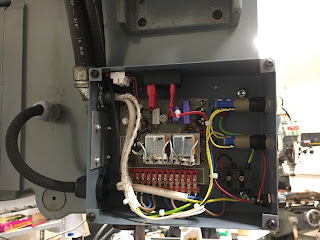
This is a trial fit of the switches. I decided to move the PCB down and to the left a bit later on, to clear the switches and make room for the SSR - you can see that in the following 2 photos. The dual switch is the one at the top - it's a modular switch system. Although they are marked "RS", they are uncharacteristically not marked with an RS part number. The front bezels, symbols etc are removable and can be customised but I'm happy with the simple up and down arrows from the original jog buttons.
This is it half finished. I later moved the outputs to another hole nearer the top to make room for the mains and interlock signal at the bottom. As you can see, the PCB has moved itself down and left.
It seemed rude and possibly ill-advised to perch the drawbar mechanism back on the top of the machine without taking it apart for inspection, cleaning and relubrication. It's fairly simple as you'd expect. It looks rather like the Kurt and Align drawbar engagement solenoids that are widely used on US Bridgeport-type machines fitted with the R8 collet system. And of course, the impact driver solution applies generally to manual machines - automatic machines tend to have pullstud toolchangers.
There's not much to go wrong apart from the o-rings. They looked fine. The splined drive parts looked to be in fairly good condition, so after a clean up, reassembly and oiling, it all went back on the top of the machine, rather like a noisy fairy on a Xmas tree.
The whole thing is hidden by a large cylindrical sheet metal cover, lined with noise deadening foam. That will go on (much) later when I have finally finished with this part of the system.
The musical bluetooth activity killed the battery in the iPhone, so more pictures will have to follow later.
Update - this is what looked like at the end of play yesterday:
Still to do:
- Configure VFD digital output for zero speed function.
- Connect 24V supply to signal cable
- Connect up pneumatic solenoid electrical and air
- Get it tested


No comments:
Post a Comment