When you use a ball ended end mill to sculpt a 3D surface such as a concave depression, you tend to end up machining much of the time with the very end of the tool, where the surface speed is technically zero. It's almost like dragging a stationary tool along the surface and of course the cutting edge approaching that centre point will have surface speeds much lower than that at the outer circumference.
If you have a proper multi axis machine (typically 5 axes), you get around this by tilting the tool at an angle to the normal at the point of contact with the surface. That's not an option with a simple 3 axis machine like mine - or is it????
A solution?
I've often thought about this issue, whether or not there are multi axis toolpaths around, as one day I will possibly want to create a nice surface finish, without wispy bits sticking out of the surface where the tool hasn't cut properly.
If the range of surface angles on the model in question is limited so that they subtend an angle less than 90 degrees, it should be possible to tilt the work over at an angle so that the surface at one extreme is almost tangential to the tool at one extreme and consequently still not normal to the surface that has the other extent of surface angle.
So, if you plan to machine a dished surface that has steepest angles that subtend angles of eg +/-60 degrees to the horizontal, the work could be oriented at an angle of almost 60 degrees to the horizontal. That way, the tool won't ever get closer than about 30 degrees from the normal. The minimum surface speed of the cutting edge will occur at an angle of 30 degrees from the centre of the tool, at about 50% of the peripheral speed (that's Rsin 30).
Best way to check this out is to cut some metal....
CAD model
I'll use some 2" square 6061 loominum, as it's fairly easy to machine - and I have some in the workshop. Also, it should work well with the 16mm ball ended end mill I bought recently from Arc Euro. Although this isn't specifically for machining loominum, they claim it'll work OK.

Being symmetrical about the central axis, the angles are the same at all 4 corners in both dimensions. I've also shown the angles subtended between the steepest faces and from the 60 degree line to those surfaces:

Then I created another component representing the stock, namely a length of 50mm square section bar stock. That's to make setting up the CAM a bit easier.
CAM options:
First, here's the conventional approach ie 3D adaptive clearing to rough out the cavity, then a finishing toolpath. For that, I thought I'd try out the "Flow" toolpath, as it's one of the latest and claims to be reasonably clever at guessing the best outcome.
Here's the 3D adaptive. Looks as you'd expect:
I was expecting a grid shaped path from the Flow option but it must have decide that a radial path would be better. Looks like a sort of flower petal shape. Not so keen on that, as it will overmachine the central area (particularly if swarf gets caught there) and leave large scalloped gaps at the edges.

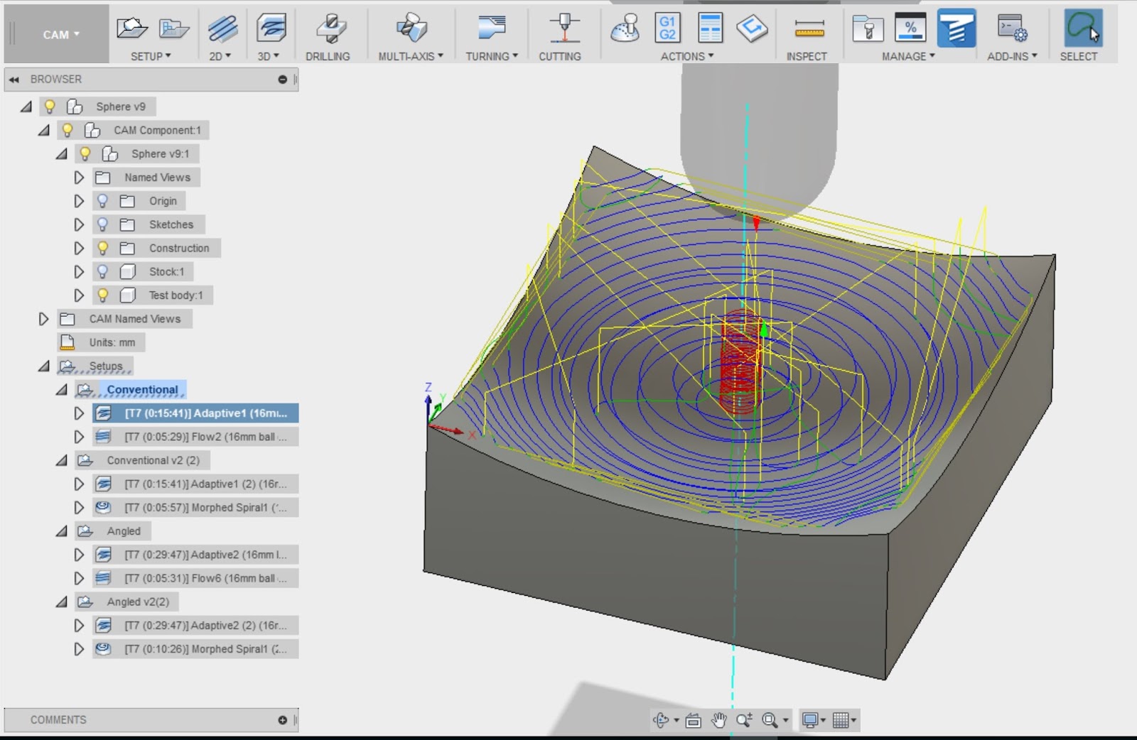
Try again, this time with the "morphed spiral". It is happy to work from a boundary, unlike some of the other spiral paths that require a central point to work out from. Could have created a point but on this occasion I couldn't be arsed. Looks a bit better perhaps:

Now onto the "angled" toolpaths. I want to keep as much in common with the "conventional" toolpaths as possible, so I duplicated them and their settings as much as I could.
Here's the initial 3D adaptive. Looks OK, without too many stray yellow moves. I had to bugger about a fair bit with the toolpath containment:

And the "flow" finishing toolpath. As before, it looks neat but is the same "flower petal" concept. Same reservations as before, so not massively happy with it:

So instead, here's the morphed spiral. I had to allow the tool to extend over the boundary so that the RH ("bottom") edge got machined. I could probably bugger about with it further but it looks good enough for the likes of me and the purposes of this test.

So there we have it.
Machining times:
- Angled - 25min (3D adaptive) / 10 min (morphed spiral)
- Angled - 25min (3D adaptive) / 5:40min (flow)
- Conventional - 15 mins (3D adaptive) / 6 min (morphed spiral)
- Conventional - 15 mins (3D adaptive) / 5:40 (flow)
Interesting that the flow takes the same time both ways, yet the morphed spiral takes almost twice as long when angled. It's what you'd expect, given that 3D adaptive is a clearing strategy while flow and morphed spiral are single pass finishing paths.
Now to do some last minute buggering about, then post some g code and cut some metal.....


No comments:
Post a Comment