Finished setting up the toolholder in the lathe. Then parted off the collet body and skimmed over the resulting face.


Done:

Facing it off:

Making a chamfered hole for the 16m ball bearing:

Fits nicely - but sticking out too far.

At this point, I dug out the dimensions for the Renishaw MP1 probe. Seems my measurement of 52.5mm PCD was spot on.

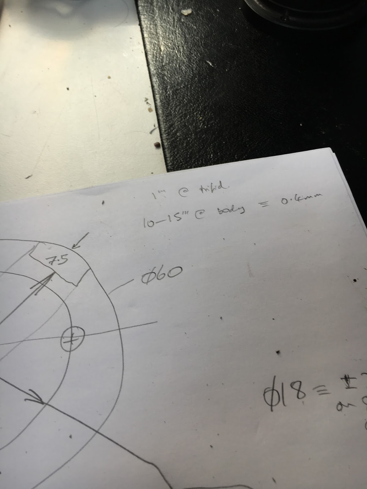
Some quick calcs. I planned to use a larger ball bearing, 'cos the collet chuck has a 6-7mm bore meaning that the original 8mm ball won't work so well. I have some 16mm balls, so thought I'd enlarge the central socket to suit. Here is a sketch that illustrates the requirement:

Seems I should aim for about 4.2mm stickout from the face of the toolholder body.
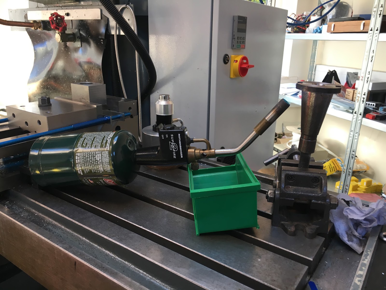
But the body is still rock hard, probably the best part of HRC60, so not much danger of drilling it as it stands. So let's give it some heat to soften it up. If I can get it to red heat and then let it cool down, I should be in with a better chance of drilling and tapping it. Perhaps I should have done this before machining the collet body off but it was a bit of fun.
I have a load of propane cylinders from our camping days, so no problem on the heat front.

That worked nicely. It now drills like a dream with my HSSCo stubby drills. Drilled and tapped the M4 on the 52.5mm PCD.

At this point I noticed that I'd screwed up. The central bore is eccentric. That's what happens when you decide to take a 16mm ball ended end mill to the bore in a rush of blood. It results in a beautiful socket for the ball but unless you are more careful than I was, you end up messing up the job. Dick head.

Apart from that detail, it seems to be coming along nicely:

Cockup!!
Hmm. Slight logistical issue - the probe body needs to clear the drive dogs that extend beyond the flange when engaged. In particular, one of them extends about 20mm from the gauge surface so that the toolholder can't engage with the drawbar threads before the dogs are aligned. Things could get messy otherwise - insert the toolholder (not aligned with the dog), engage the impact drive and crash the dogs into the side of the holder. Not recommended.
Change of plan - need to either start again with another toolholder (I can forget that, as I don't have one) or weld a plate on the front (messy, lots of work and I don't have a suitable piece). Or mill a couple of clearance slots in the sides of the probe body? I favoured the latter, so that's what I did.
Machining clearance slots:
Seems a bit extreme to chew lumps out of a precision probe head but that's what is required and as long as I don't break through into anything critical, it will give me the neat solution I'm after.
I will have to remove the serial number label and the model lable on the opposite side. Managed to get them off with a scalpel. They are loominum, with double-sided tape to hold them in place.

This shows what is required - this is the longer of the 2 drive dogs but you can't be certain which way you will inert the tool, so both sides must clear it.

On the (manual) Bridgeport clone. It's a 12mm HSSCo slsot drill. The corners of the tool are a bit buggered so it doesn't cut very well. But I can't be arsed to change to a better tool. It will be good enough and I will debur it afterwards.


Done. Not the best bit of work I've ever done but it's fit for purpose, no cockups (this time) and it didn't break through into anything unexpected.

Dry fit looks OK:

Yes, I messed up the PCD holes. Third time lucky. The ball is seated in a 90 degree CSK hole, just like the hole in the probe body. It protrudes about 5.5mm from the face of the holder. That leaves the specified 3mm gap between the body and holder when assembled.

Finally assembled again. The complete probe assembly is now the same length as the original adaptor without the probe body. So now I have a probe that is over 2" shorter.

It's now much closer in length to the other normal tools. The Martest 3D indicator is the red thing - it's just too lon to be much use on this machine. Perhaps I should just fit it to a 30 taper toolholder and use it on the BP.

Heheh - job done. Last part - realign the probe again. It's rather like setting up work in a 4-jaw chuck:
It's better than 10um - probably about 5um.
There.


No comments:
Post a Comment