There seem to be several key parameters that I'll need to get right. That's pretty clear when you trawl through the parameter list and some of the RT notes and bulletins. And I have to factor in my non-unity pulley ratio (1.1274 at last reckoning).
However, I have made some important realisations / pragmatic judgements:
- Mostly, RT seems to be done at several hundred RPM, so (for now at least) I'll simply plan to do all RT in the high range (direct drive, rather than using the back gear reduction stage).
- Given that I will have only one spindle drive ratio, all I have to worry about is getting the right feedback info from the encoder. It's pretty clear (as expected) that the RT process uses the spindle encoder signal to set (synchronise) the Z axis movement.
Despite what it says in the manual, there is no way to tell the controller that the encoder is actually mounted on the motor, not the spindle. Parameter #36 claims to be able to define the encoder as being motor mounted but when you do some basic tests it soon becomes apparent that this isn't the case. Pity.
- I'll be doing most of my RT with the taps mounted in a tension compression head anyway. So the accuracy of the Z axis synchronisation isn't enormously critical.
Parameter settings:
- #78 (spindle speed display) looks quite critical.
- Bit 0 can select spindle speed based on the encoder signal (#35) and encoder count (#34) (value "1") or on the programmed speed, pulley ratio and gear ratio (value "0").
- Bit 1 can force synchronisation of any dependent feedrate when the spindle speed bogs down below a preset % (#149) of the set speed. Add 2 to the value of #78 to make this happen.
- Bit 2 will force "wait for spindle at speed" for G1, G2, G3 etc.
- I've gone for a #78 value of 3 here. That displays the speed based on the encoder feedback and will synchronise the Z axis feed with the spindle movement if the drive bogs down. It won't protect against belt slippage but should cope with motor stalling.
- #33 is the pulley ratio. Technically, it's about 1.127 but it seems I'd be better leaving #33 at 1.000.
- #34 is the encoder count per rev (CPR). Again, technically this is 8000 for the Omron clone encoder fitted here. But I've concluded that it's best to frig the pulley ratio etc by setting #34 to 9020 and leaving the pulley ratio at 1.00 as noted above.
- #35 is the axis associated with the encode signal. In this system it's axis 5, so the value of #35 is 5.
- #278 is the number of DPs for the displayed value of the spindle speed on the screen. I've left this at zero.
Trials:
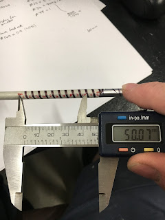
The only way to check is to do some tests. As I'm not made of machine taps, I wrapped some masking tape around my 6mm reference tool and mounted a marker pen in the vise. With suitable G54 coords, I can run a simple tapping program that will run a pen down the side of the tool. Obviously it's helpful to go for a coarse pitch and to "cut" quite a few threads (like about 10 for convenience) so you can measure them with reasonable accuracy.
Here's the basic command:
G84 Xx Yx Rx Q5 Z-60
- G84 is the RT code for clockwise (CW) threading.
- Xx and Yx are the X, Y coords of the hole
- Rx is the start position, just above the hole start (mm)
- Q is the thread pitch (mm)
- Z-60 indicates the Z coord of the bottom of the hole
So my short program looks like this:
T2 M6 ; Load tool 2
G43 H2 ; Use T02 length offset
S200 M03 ; Spindle 200rpm CW
G84 X0 Y0 R1.0 Q5 Z-60 ; RT move
G80 ; End of canned cycle
Worked quite well. You can easily remove the tool and wrap new tape without disturbing the pen.
Measured 10 turns at 50mm, so seems to be a success.
Conclusion:
- I'll do all my RT in the normal high range. In fact I can't yet see any need to ever engage low speed on this machine. The time may come - perhaps boring out large diameters - but although I'll leave the door open for it, there's no need to get into it right now and complicate the RT business. I got auto range selection sort of working the other day but it seemed a bit of a carry on.
- Best to leave the pulley ratio at 1.000 and to frig the encoder count to get the correct number of motor turns. That conclusion is based on the endless tests I did this afternoon. By increasing the declared encoder count by the pulley ratio of 1.1274 ie increasing it from 8000 to 9020, I get the spindle speed that is commanded. There's no way to get the displayed spindle speed correct without perhaps some messing with the PLC code but that's not a big issue for me. The VFD and display speeds are about 4-5% out but nothing in this system is critically dependent on the speed being accurate. RT is based on the encoder count and the "bogging protection" should account for any significant variation in speed.
- I'll probably be doing most of my RT with a tension compression head anyway, so much of this is uncritical.
There.


No comments:
Post a Comment