I have a nice piece of 2" square cold rolled steel to make this from. CRS isn't perhaps the easiest material due to the stresses that are built in during the rolling process but I'll be facing off the skin which should hopefully get me past the worst of it.
As I see it, my machining process will look like this:
- Drill and bore the central opening in the lathe. It's tempting to do the whole thing on The Shiz but I'm sceptical about the possibility of achieving the tight tolerance onto the ballnut without having to make multiple passes and repeatedly frig the cutter diameter compensation. Then I may over cook it and have to start again. Instead, I can model up the stock with its hole already bored and import that into the CAM environment.
- Face off the "top" surface, then rough and finish the external profile to full depth. Chamfer edges.
- Remount with "rear" face upwards, to allow machining of the annulus around the fixing bolt register. This is required to make the cylindrical face (that mates with the surface of the quill) machinable. I could easily design something here that is pretty much impossible to produce.
- Remount with the "bottom" face upwards. Face off the remaining stock, chamfer etc.
- Finally, drill and bore the fixing hole, then mill out the 3mm slot - that'll take a while.....
- I'll manually drill and tap the M10 hole for the pinch bolt and the M4 holes for the DRO head etc.
Stock body creation:
My basic lump will be the aforementioned 2" square stock, 66mm long (finished part is 64mm long). So the starting point is a simple extrusion:

Now I need to cut the bore into this, to represent what will come off the lathe. I want any changes to trickle through to the stock model as well as the final CAD / CAM models. So I will use the CAD model for the bracket to create the bored holes through the stock by using the Boolean "combine / cut" operation. I grounded the model and stock first to avoid any unplanned changes....
I created a simple cylindrical body concentric with the bore slightly larger diameter than the biggest diameter and longer than the extents of the stock. The initial operation to combine / cut the stock body with the bracket body obviously generated additional features I didn't want, such as the 3mm slot, fixing hole bores, chamfers etc:

Simple way to fix that is by direct editing them ie select and delete. This generated a simple cylinder with a step at one end:

It was then a simple matter to use this as a tool to cut the bore in the stock:

So this is my starting point for the CAM proper. I need to manually machine up the stock so that it looks like this.
Takes seconds to make a drawing of this simple part:

If you make the component and the stock visible, then turn the opacity control down, you can see the wannabe component lurking inside the stock. All I have to do is liberate it:

Pre-machine the stock in the lathe:
Chopped off the required length in the bandsaw, marked it out and centre punched the hole position. Set it up in the 4-jaw vise within a thou or so:

Drilled it out to 25.5mm. This Dormer drill is still cutting very nicely:

Bore it out to 28mm and counterbore to 32mm:

I dug out the ballnut. It's got a ground finish and is pretty much cock-on 28mm. Nice tight fit - needs to be inserted dead square:

Deburred and now ready for The Shiz:

Here's one I made earlier:
As well as the ballnut, I dug out the loominum bracket I made before. Not strong enough, hence the change to steel.


A couple of features to take note of - the top of the feature that contacts the quill through the slot in the head should be radiused to minimise the loss of travel. And there is a relief to avoid the body of the bracket clashing with something on the head - will need to check what that is and probably include it in the model.
Toolpaths:
Face off the top of the stock, down to model top. The origin is actually set level with the shoulder in the bore and on the centre line. So the accuracy of placement of the shoulder wasn't critical.

3D Adaptive to rough out the shape of the bracket.
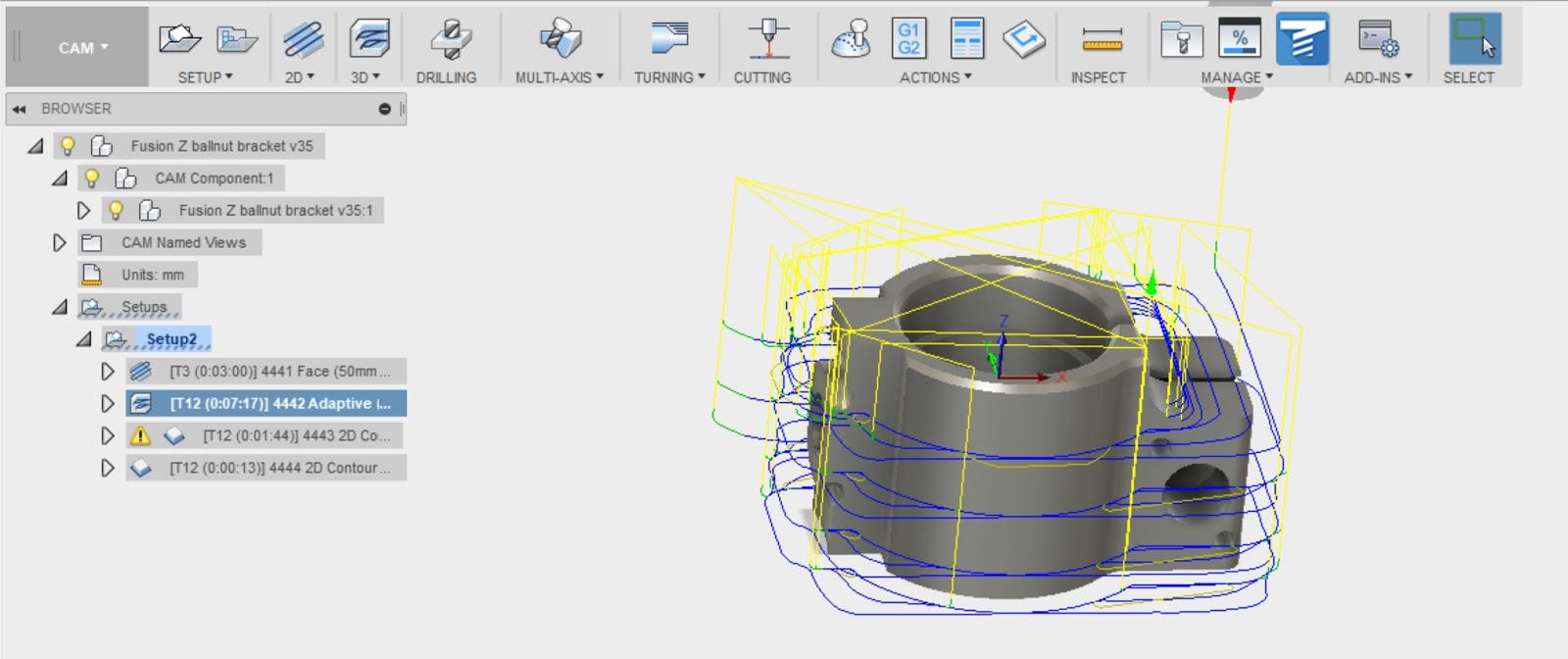
2D Contour to finish and clean up the outside.

And another 2D Contour to create the top end of the cylindrical surface. Can't do the bottom half, as the boss is in the way.

The tool isn't really long enough to reach down to the full depth of the part (36mm), so I need a longer tool. I've ordered a couple of 12mm dia end mills (40mm useful length) to do the job. But the toolpaths will be valid in the meantime.
Problem with 2D Contour toolpath - profile selection:
Had a right royal PITA trying to define the profile for the 2D Contour operation in particular and the 3D Adaptive to some extent. On the face of it, you simply select the bottom edge of the model and then click the red outline to deselect any segments you want to omit, or click any you want to add. But this is not one of Fusion's finest jobs - I found that I simply couldn't select the outer edge and not the inside profile. I've already machined the inside, so don't want it to attempt that.
Selecting part of the profile was OK:

But trying to extend it didn't end well:

Didn't seem to matter what I tried, I couldn't get my profile to be recognised.
Worse than that, once I'd finally managed to define a sensible contour after much buggerage involving patches and deleting chamfers, the toolpath generated had loads of silly moves around the area of the boss. None of the myriad settings I changed would get rid of them. WTF????
Worse than that, once I'd finally managed to define a sensible contour after much buggerage involving patches and deleting chamfers, the toolpath generated had loads of silly moves around the area of the boss. None of the myriad settings I changed would get rid of them. WTF????

A quick post on the Fusion CAM forum came back with a couple of suggestions:
- Create a sketch from the model and use this to define the contour. That works but it clearly isn't locked to the model, so any changes to the model would probably result in a bad toolpath.
- Fill in the slot and bore - but choose "create new component" so that the "filling" is optional and doesn't affect the underlying model. It can be used to create the toolpath but doesn't require any changes to the CAD model. That's another neat workaround that might work where sketches don't.
- I actually used the "sketch" approach - but instead of creating a new sketch, I was able to go back to the original sketch that defined the model and use that to define the toolpath contour. That seems like the best solution.
Finally, a solution that works and doesn't require removal of chamfers and addition of patches:

Grrr. That was a complete ball ache.


Hi there,
ReplyDeleteDo you sell parts for a cnc conversion such as this bracket?
Hi there,
ReplyDeleteDo make these parts? would like to convert my bridgeport as well to cmc