The conventional operation:
Set part Z0 using the Renishaw probe.
Ready for action. Rubber pants on!! This is tool 7, the 16mm ball ended end mill.
And we're off!!
Proceeding nicely so far....
Almost finished the first operation (3D adaptive) to rough out the cavity:
After about 20 minutes of operation, nothing is heating up to speak of. The mains transformer is the hottest part, mainly due to core losses.
Onto operation 2, morphed spiral:
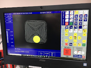
This is the groovy toolpath graphic display:
Almost finished the second operation (morphed spiral). Looking good so far....
And there we have it:
Out of the vise, deburred etc. As ever, it feels a lot better in the flesh than in the pics but sure enough, the finish isn't exactly mirror smooth.
"Angled" operation:
The CAM was covered in a previous operation. The required angle of the stock is 55 degrees to the vertical ("tipped more than half way towards the vertical"). I used the digital angle gauge for this. It's not highly critical but it claimed I was within a few tenths of a degree.
No point attempting to use the Renishaw probe to set zero here, as there is only one orthogonal(?) face so I just used the pointy tip of reference tool T1.
Sorted - ready to go. Quick dry run / air cut to sanity check that things are OK. Running with T1 in place instead of T7 should allow the tip to trace the path about 20mm above the stock. GAH!! That stupid fat bloke had appeared in the workshop again and touched off the work origin using T1 reference tool. BUT HE TOLD THE SYSTEM IT WAS TOOL 10, NOT TOOL 1, THE DOZY FAT BASTARD. What a twat. So first move was to make up for the extra 80mm difference by sending the reference tool into the stock.
Nobody died, I didn't actually shit myself and the tool survived. The servo lost a few steps ie work coordinates moved a little bit and the toolholder has a nice loominum sheen on it. There's a little gouge in the stock but it'll be fine....
Start again. That's better. My ring piece was twitching a bit by now but it settled down after a few mins. Obviously there is a fair bit of (stock) stickout, so expected a bit of chatter on the heavy cuts but apart from that it seemed happy.
This is the side view of the toolpath shown in the groovy graphics:
Coming along nicely....
Although you are recommended to devote the PC / processor exclussively to CNC operations (even disabling Windows updates etc), I seem to be able to play muzak and update this blog with text and pics as it runs. I suppose the CNC operations are only running on one of the cores in the i3 processor and I'm using the other (2 actual cores, 4 virtual cores).
The results:
Went well. Nothing got broken, nobody crapped themselves:
"Conventional" toolpath on the left, "angled" toolpath on the right:
Looking through a watchmaker's loupe, the pattern on the angled part is mainly due to the finish on the cutting edge of the tool. The picture isn't very good but this was taken with an iPhone.
If you look closely at the "conventional" surface, you can see a spiral finish in the middle of each individual track. The cutting action is poor:
I have only 25 passes in each of the finishing operations, so the finish has some scalloping obviously. Some observations:
- As you'd expect, the "conventional" operation leaves a visible spiral at the centre of the path, particularly where the tool is perpendicular to the surface. That's the whole point of this experiment.
- Most of the surface finish in the "angled" path is due to the finish of the tool edge itself. If the tool were polished / honed, those look as if they would be much improved.
- The "angled" operation doesn't end up with evenly spaced passes - the more vertical face has passes that are further spaced.
- The conventional path produces a fairly "square" toolpath, whereas the angled path produces more tracks that are in the "horizontal" ie Y axis direction.
- There are some scuffs within the "angled" scallops, presumably where there was some minor recutting. I didn't have the coolant on here, as I have no guards fitted. Ironically, the angled position would help the swarf to clear, so I would expect a better finish when the coolant is used.
Overall overall - good result!


No comments:
Post a Comment