Servo drives:
Now to remount the servos drives. I have 3 of the CNCdrives servo drivers and a Leadshine stepper drive (fpr the 4th axis). I'll hack down the old heatsink (it originally came from the ancient Hitachi VFD that came fitted on the new machine from the factory). By mounting the drives standing up on their rear surfaces, I should be able to reclaim some of the valuable space on the baseplate.
First, mark out the mounting screw hole positions, drill and tap (M3), then chop the heatsink down to size. It's already peppered with holes from its first life as a Hitachi VFD and subsequently as the first iteration of the updated Shiz. Did most of it by hand with the Taiwanese 6x4 bandsaw in vertical mode:

Then finished the last cut in normal mode, as I was getting a bit sick of pushing and guiding by hand. The bandsaw's in an awkward place.

Clean up the sawn faces a bit:

Dry fit - seems to have worked out OK:

The transformer and VFD roughly in position:


Still a few useful bits to be recovered from the old tray:

The "ALM" and "INTH" signals on CN3 of the old controller. Can't recall what these did but we can see they were connected to the servo drivers.

The white/orange and orange wires are the step and direction inputs to the drivers respectively. White/brown and brown are the 12V supply and 0V respectively.
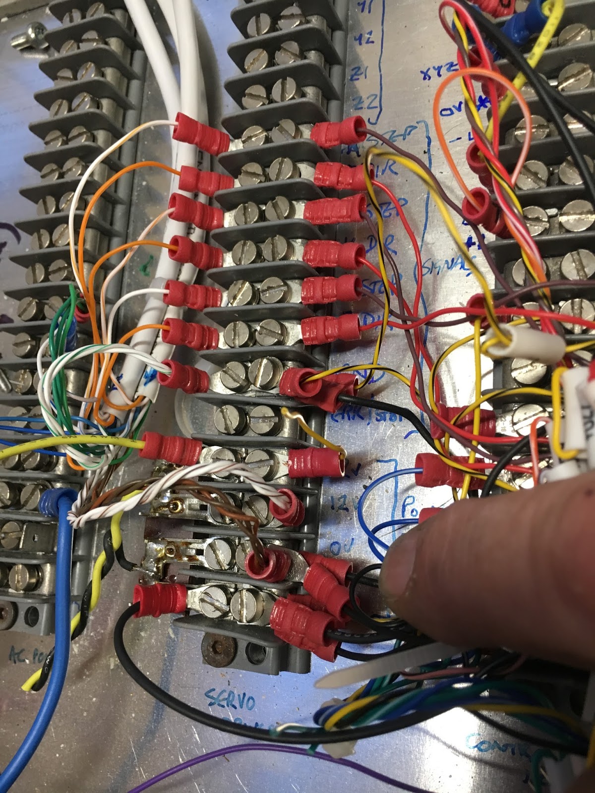


The CNCdrives servo drivers use RJ45 connectors for the logic supply / drive signal connections, so I should be able to reuse these.

The output of the transformer goes straight to this beefy bridge rectifier. It was recovered from the old Hitachi VFD. There's no soft start / inrush limiter on this side of the transformer - I fitted mine on the mains side, since the inrush current to these large transformers often includes a massive current spike due to the cores saturating as a result of the remanence in the cores. The inrush limiter recommended by Centroid is simply a PTC between the bridge and the bus caps, so can't do anything about the transformer currents.

So this is how I did it. There's a programmable time delay relay (the little white module second from the right), a soft start resistor (22R) and a larger relay that shorts out the resistor after the programmed delay. Works nicely. The time delay is something like 1/2 second, during which time the caps become mostly charged up.
I used a similar soft starter on my massive Miller Interlas TIG welder. In that example, the resistor is 10R. Too small a resistor and you don't limit the saturation current enough to much help, too big and the cores aren't given enough mag current to bring the flux back around zero.

I seem to have a spare left over from the welder build. I wonder if this would be a neater solution that the solution above. Need to check out this timer relay - it's a beefier relay, so might be able to do the whole thing with one component.

It's a pretty versatile device - "Analogue Timer, Module, 86 Series, Multifunction, 0.05 s - 100 h". You can select various modes with the DIP switches, including the one I want, namely a programmable time delay. The data sheet shows how to set it up.
For my part (type 86.00), simply set switches 4, 5 & 6 in the up position for "AI" mode. The datasheet shows how to set the time duration using the switch positions 1-3 and the blue twiddly knob.

So the soft start will simply comprise this fancy relay and a 22R metal clad resistor on the transformer primary. It will take care of itself every time it is powered up.


No comments:
Post a Comment