
It would seem rude not to remove the cover to see what has been going on in there.

This is the PCBA. The differential line driver is a TI part AM26C311. It's similar to the part I bought to make my own. Looks likely to be a fairly accurate clone of what I'd imagine the original looked like. Probably the result of running off an unscheduled extra batch of products in the approved factory and them getting rerouted on their way out of the factory.

I'd already established that there wasn't much chance of fitting it to the spindle, so instead I focused on connecting it to the spindle motor. There's already a spindle brake on the top of the motor and I'd rather not lose that in case it is helpful for locking the spindle during tool changes etc.

It got a bit rusty during its time on my building site(!). The whole top part rotates with the spindle, so those six M3 screws could come in handy.

Some quick measurements and sketches. At this point, all sorts of machining operations come to mind. But I'm a lazy bastard as well as a fat one, so I think carefully about how to achieve maximum outcome with minimum effort. My solution is simply a piece of 1" loominum bar with 3 holes in it - the centre one tapped M5 and the outer holes being M3 clear. Simple - and quick.

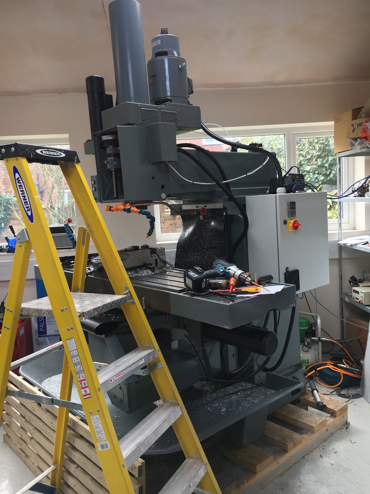
Yes, it's quite a way up - I'm standing on the machine table which is over 1.1m from the ground and it's almost at head height.
The M5 bolt, turned down to a convenient 6.0mm diameter has a 60 degree point, so it locates conveniently in the centre hole on the end of the motor shaft, aligning the part. I can adjust it carefully so that the bracket is aligned - without the bracket sitting proud of the shaft surface. The DTI showed that after setup it was concentric to about 5"', which is fine - I'm sure the plastic Oldham coupling that came with the encoder won't be anything like as good as that.

Bang a 16mm hole in the cover to clear the Oldham coupling:

The encoder isn't mounted yet but you can see the plan coming together:

Here it is with the standoffs fitted and the encoder aligned concentric with the motor spindle:

I ran the screened encoder cable down the motor conduit. It was only just about long enough at 2m. That required me to solder the 9 way D connector on in situ.

It just reaches the encoder connector on the Acorn board. Not absolutely ideal but I've done a lot worse on the bodgery front:

Job done - and it works. Of course, the controller is expecting the encoder to be a spindle encoder, not a motor encoder. But either way, it won't do rigid tapping without an encoder.
If the controller can't be configured to take this as a motor speed signal, perhaps I could divide the declared encoder count by the gear ratio (about 0.167) and only enable it for tapping. We'll see - but getting answers out of the Centroid team is like drawing teeth....


No comments:
Post a Comment