I connected up my home made Tool Touch Probe that senses when the tool makes contact. It can be a pretty simple design on the face of it but the main complication is the need to spring load the touch surface. If you use a rigid touch surface and send a carbide tool into it, you will chip the edges and bugger the tool. On the other hand, you need to ensure the spring loaded touch surface returns consistently to the same position every time after being depressed by the tool. So you need a reasonably flat and free moving pair of mating surfaces within the assembly. In mine, I have a simple spring loaded plunger and a Turnol body.
I made the thing a few months ago but it needs some modifications to work with the Centroid controller:
- The Centroid wants to see a loop back circuit to tell it that a touch probe has been connected. That allows it to control the search speed - and it also prevents you from trying to detect a tool when the probe hasn't been plugged in. You could easily send the quill into something unforgiving in that situation.....
- The standard wiring arrangement for the Centroid TT-1 Tool Touch Probe uses a 3.5mm audio plug (cable) and socket (probe). But they have chosen to use the shield / external housing for the touch surface connection. That's a complete PITA for my machine, as most 3.5mm panel mounting sockets have a grounded shield by the way it's mounted on the panel. So I changed the connections around. It's not going to be a big issue, as I won't be interchanging my probes with genuine Centroid ones. Mine is connected like this:
- Probe signal - tip (blue)
- Probe detect - ring (green)
- Probe ground - shield (black)
- So I had to rejig the internals of my tool touch probe. TBH, that made a bit of a mess of what was otherwise a neat and simple solution. But It'll do for now.....
I discovered that if you try to send the table or quill to the extremes of travel before you have homed the machine, the limit switches don't function as limit switches. Hmmm, perhaps I'm missing something. This needs closer investigation.
Here are the component parts - insulating body (Tufnol), steel touch surface plunger thing, steel spring (a coiled up length of stainless steel TIG welding rod) and a 3.5mm audio socket:

No, it's not pretty. The socket and an M6 screw hold the spring in place.

Looks OK from the outside:

But it's a pig's ear inside. My excuse is that "I will tidy it up later once I know it works". That old chestnut. The body of the socket has to be insulated from the spring, the spring has to be connected to the "tip" contact and the "ring" element has to be shorted to the "shield" ie body. Luckily you can't see this mess from outside unless you pick it up and stare up its backside.

Plugs into a socket on the cabinet:

Here is a short vid showing it in action:
The tool lengths returned over 8 consecutive tests were all either -152.857mm or -152.863mm. That's 6um difference, which is a bit odd. With a 5000um per revolution ballscrew and 2000 pulses per rev, that's 2.5um per step - not 3um or 6um. I suspect some form of imperial measurements actually happening under the hood. But quite why I see a 6um step (ie not a 3um step) is unclear at the moment.
The "-153mm" refers to how much shorter the current tool is relative to the reference tool. However, if you have not homed the machine yet, I suspect it assumes that spindle top (home) is zero position with the reference tool fitted. As my quill has a max movement range that is not much more than 150mm, clearly it has lost sight of the fact that my reference tool was set at around 100mm yesterday.
Renishaw probe:
Now onto the butchered Renishaw MP1 probe. I need to stop the connector being pulled out, so I have used my tinkering skills(?) to solder a small ring crimp onto the brass body of the 5 pin DIN connector. It's a pretty shitty quality connector but will also do for now. The loop back and probe signals will happen here, inside the cover.
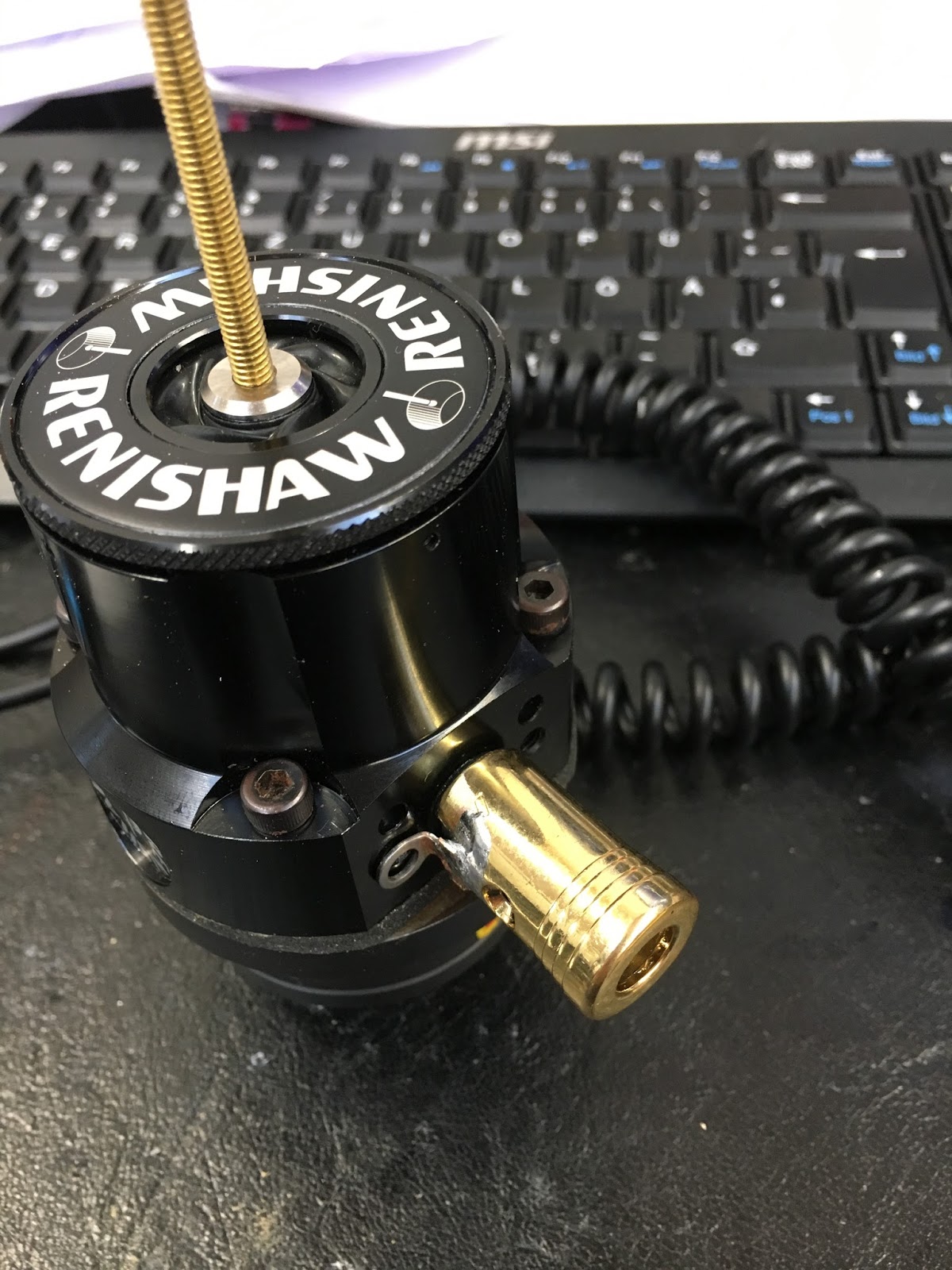
So now I will need to find a 3.5mm cable and solder it onto the pin assembly. Then see how badly I can bend the probe...
Note the brass screw currently fitted in place of the ceramic / sapphire probe tip. I will break that later once everything is up and running.
Note the brass screw currently fitted in place of the ceramic / sapphire probe tip. I will break that later once everything is up and running.


No comments:
Post a Comment