The Z axis motor was a complete PITA to disconnect, as the encoder cable is routed right through the guts of the motor. Managed to get it down onto the machine table without damaging anything, where it is easier to work on:

The motor mounting bracket is a casting that sits on the side of the head:

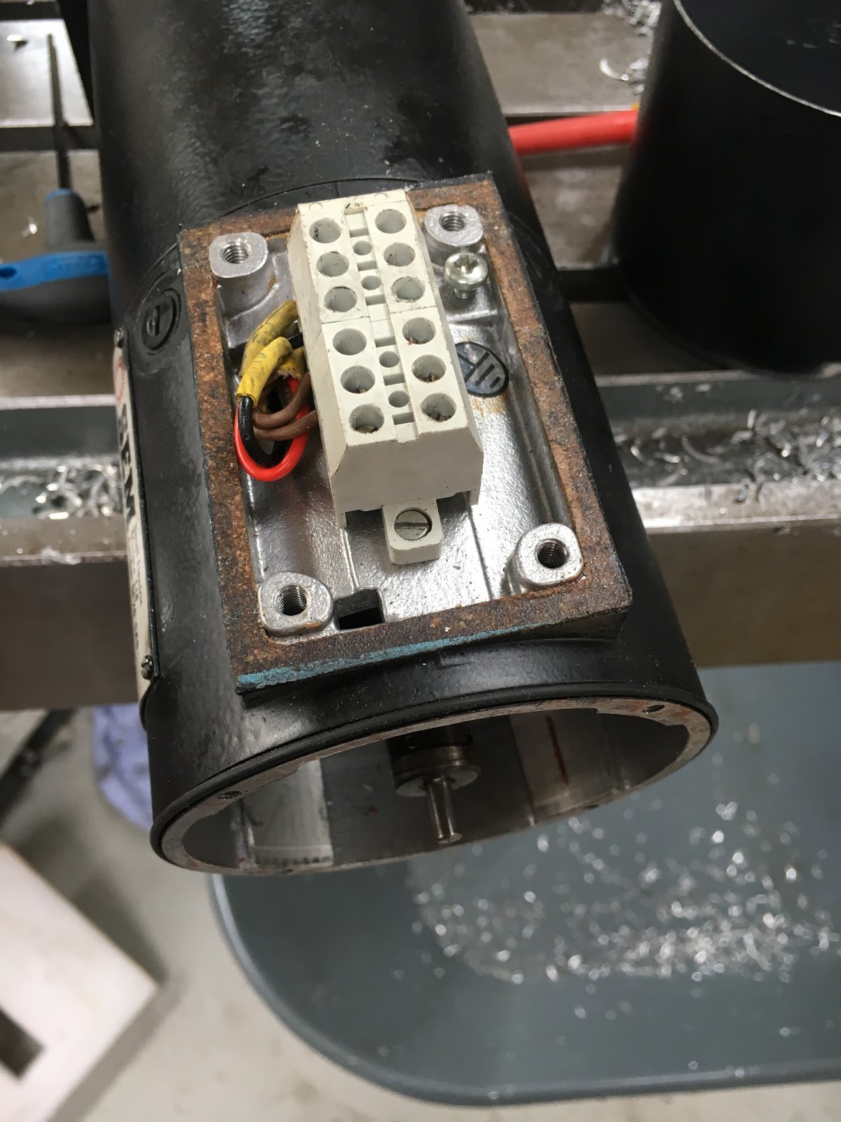
Inside the terminal box on the side of the motor is a connector for the various connections. "T1", and "T2" are the temp sensor, "K1" and "K2" are the tacho signal and "A1" and "A2" are the armature connections. I only need the latter.

Once the encoder has been removed, the tacho assembly is exposed. It has 4 brushes on a carrier. Removing this exposes the guts of the tacho assembly.

The special rotor assembly is just held on the shaft with a couple of grub screws. Fancy little thing - looks expensive. The old analogue servo driver circuits used the tacho voltage to give the feedback signal required for full PID control. However, modern digital drives can derive the same information without needing this analogue signal. So this little lot can f*ck off for starters. The coupling connects the position encoder to the shaft.

The connections are simpler now.
I'm going to replace the conduit with something more modern, so need to open the gland hole out to 25mm. Simplest way is just to mount it in the 4-jaw and use a 25mm drill:


There. You can see the Oldham coupling used to connect the encoder here - and the space left by the removal of the tacho assembly:

Back together again:

I'll keep this on the bench for now so I can test the servos. Mustn't forget to reconnect the encoder cable first!!


If it is not too late - don't bin the tachogenerators ! They were ferociously expensive back when these motors were current (around £350 + Vat for the armature & £100 for the brushplate 20 years ago IIRC) & I seem to recall that they are NLA from SEM. The armatures do occasionally go open circuit on 1 winding, so all the Bridgeport Interact owners still out there could be potential customers (Interacts used SEM MT30 motors as well). No great loss not bothering with the termal switch - by the time they tripped the main armature had usually burned out anyway !
ReplyDelete