Sunday, 16 June 2019

Trouble at t'mill!!

Indexable insert milling cutters vs APXX inserts:
WTF?? I have a Korloy AMCM3050HS cutter with pukka APMT1604PDER-M2 inserts, yet I am getting a completely shitty surface finish. It's obviously rubbing instead of cutting. I used a fresh set of inserts, yet the edge looks unhappy after just one pass of only moderately heavy cutting. WTF???

Here's the edge of the insert. Not easy to photograph using an iPhone but you can just about make out the suboptimal end result.


Let's do a trial cut again, at 1200rpm. 


The photo hardly does justice to the crap finish. Enabling coolant half way through made no obvious difference. This is rougher than any self-respecting bear's arse.


By way of a sanity check, here's a slot made by a Mitsubishi BAP390 series indexable cutter (16mm dia) in the same machine and workpiece at 5000rpm. It's a different result altogether. And yes, those are genuine Mitsubishi inserts and a genuine Mitsubishi body. 


What's going on?
There's no such thing as a universal fit AP** insert, it seems. And even within the range of one manufacturer such as Korloy, there is a bewildering range of insert geometries, not just the chipbreaker shape. What I didn't say above is that the APMT1604PDER are made by Mitsubishi. Clearly the APMT1604PDSR inserts recommended by Korloy are subtly(??) different. 

Here's what Korloy recommend for this cutter:


And the Mitsubishi insert that is apparently functionally similar:


You can even download a STP file for the insert model. This shows the 15 degree clearance angle at the bottom of the insert, for instance. Ideally I'd also have a model from Korloy to do a comparison against. However, you can imagine that if the Korloy holder lacked at least 15 degree helix angle, the Mitsubishi insert would rub. Is this what is happening? Doesn't appear to be the case - visual inspection shows a clear clearance angle. However, the inserts really don't seat properly in the cutter body. 

For now, I'll order up some of the official Korloy inserts - one set each of H01 (uncoated, for loominum) and PC5300 (for steel). The MA suffix denotes the sharp chipbreaker geometry and ideally I'd manage to source some light duty, sharp inserts for steel but Aliexpress didn't offer me any.

These will do for the loominum cutting inserts:


 And these for the steel cutting applications:

Conclusion:
So, the lesson seems to be to look very carefully at the manufacturer's data for the cutter body and be careful to obtain only the recommended inserts, rather than some generic part, even from a reputable manufacturer. Or at least I think that's the lesson here. When I get the new inserts in a few weeks time(?), I'll be able to confirm that hopefully. Meanwhile, for facing off and squaring up the stock for the yoke, I'll have to use something else, such as a solid carbide or HSSCo cutter. Perhaps I should have used the lathe after all.....

Mill turning in Fusion?

Post processors, CAM setup etc:


Lucas Is Busy

Ballnut machining

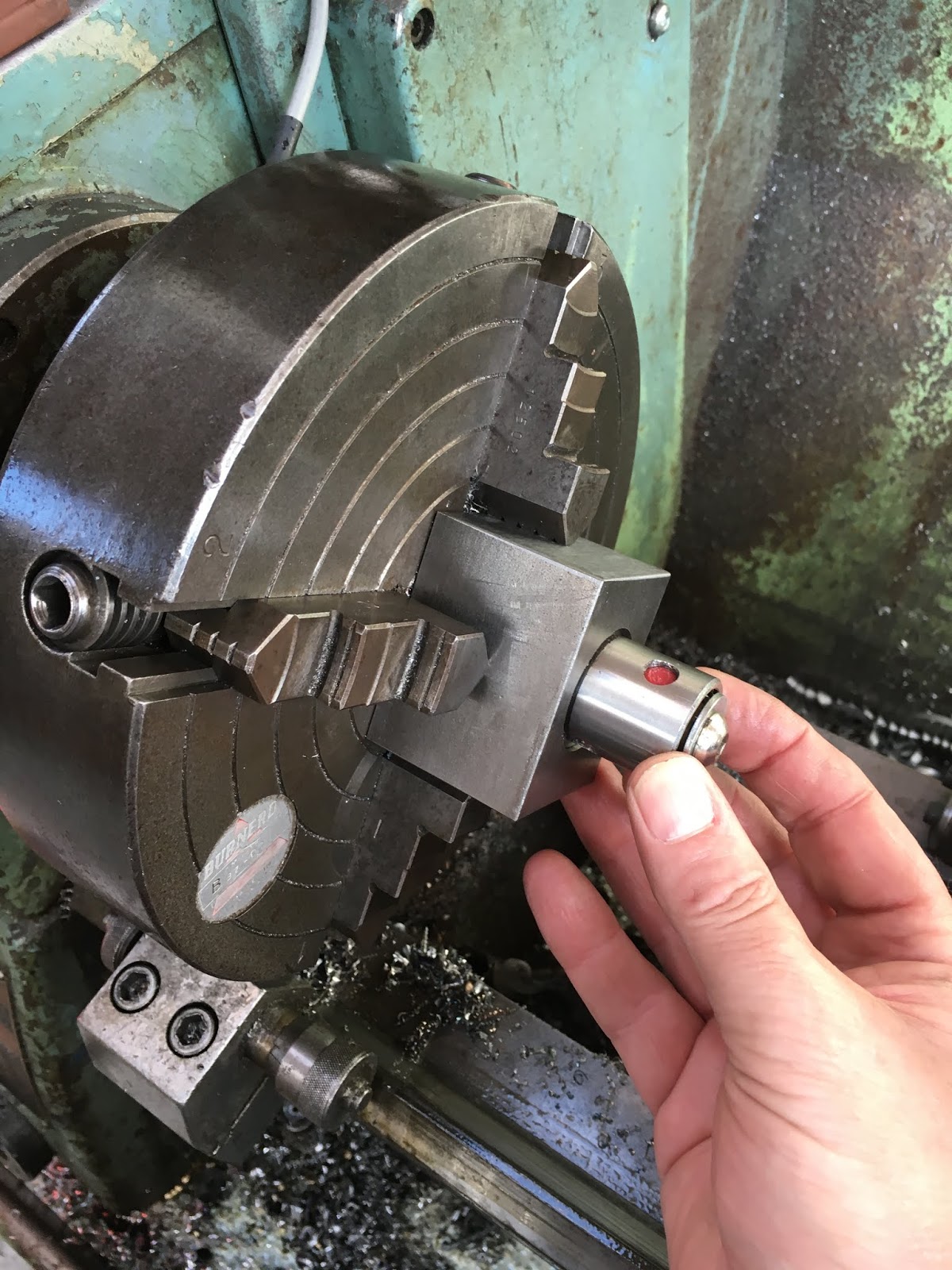
Removing the ballnut from the ballscrew assembly:
I'm going to have to machine both the ballnut and the ballscrew, so first of all I'll need to remove the ballnut without my balls dropping, fnnnaaaarrrr. This is the method I used before:

The shorter brass (bronze?) "keeper" piece on the left will sit inside the ballnut, holding the balls in their channels and is in turn held in place by an M8 screw / washer on each end. The brass piece on the right is only used during the removal operation. It's bored out internally at one end so that it slides over the reduced end of the ballscrew.


Ballscrew removed, now to remove the temporary extension tool:


Done, with the keeper secured in place:


Ballnut machining:
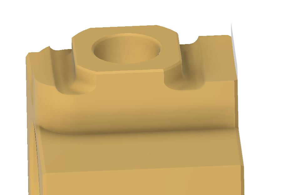
Here's what I need - the 15mm wide "nose" needs to be machined, otherwise the ballnut flange will foul the machine head casting. It actually requires machining to a depth of 7.5mm below the circumference, although that dimension is not shown in the drawing:


But before doing any machining, it's essential to prevent any swarf getting inside the ballnut. Masking tape does the trick:


Although it's hardened carbon(?) steel, a carbide end mill is more than capable of machining it. I have used a 3/8" end mill I acquired in Canada. Presumably made of mystery Chinesium carbide but it's not something I'm likely to want to use for anything important.


Came out all right...

Friday, 14 June 2019

New components for the Z axis assembly!

New goodies:
The new, smaller (10t) pulleys arrived today, as did the Chinesium ballscrew. 

The ballscrew: 

...was skilfully wrapped, in the traditional Chinese fashion. 


It's supplied with the default machined ends, which are intended for the standard ballscrew bearing bracket things. Arguably it would be helpful to incorporate this into my design without needing any further mods - or as few as possible. The main feature that is missing is some form of keyway for positive location of the pulley. Having said that, I plan to use a grub screw to lock the driven pulley to the ballscrew, so I may get away with machining a flat.


I said keep it simple, fatty!

I seem to be forgetting that I'm trying to keep this as simple as possible. I found previously that the quill stops some way before the yoke gets to the lower casting feature. I may as well make the height of the yoke 10mm shorter and mount the ballnut in its natural form (ie as it arrives, without needing any machining), with its flange outside of the yoke. Then, despite the additional height of the fixing bolts (6-8mm), there is no impact on the travel and considerably less ballache involved in making the components up.

Something like this - 30mm height, giving ~48mm overall height, including some lock washers. The relief channels are 3.2mm, to allow a 3mm ball end mill through. May not be essential but it seems good practice to avoid sharp edges (stress concentrators). 


What's with the complicated mating feature?

Why the complicated mating feature?? Well, I actually consider this one of the "strengths" (sorry!) of my design, since a strong and rigid connection between the ballnut and the quill is critical - and this is the main area where most existing solutions seem to be rather weak, literally. The systems such as Elrod and Southwestern Industries have a bit cantilever / overhang due to the position of the ballscrew away from the quill. And BMS250's yoke doesn't seem to have much contact with the quill. My widely spaced contact areas give a much reduced tension on the connecting bolt and a more rigid overall connection. To my mind, anyway.

I could finish machine most of these features from above (as oriented above) with a single ball end mill, once the basic steps have been roughed out. Although a ball end mill won't give as smooth a surface finish on the large radius surface as the side of an end mill would, I'm sure I could make it good enough.

And, yes, I have got rid of the pinch bolts and pinch slot....

Pulley keying:
I also specified the smallest pulley I thought I could get away with. These are the "XL" (imperial) system, with a 3/16" tooth pitch, so a 10t example has a 1/2" root(?) diameter. The motor spindle is 8mm, so that only leaves about 2mm of metal to fit a grub screw to. It's looking as if I may need to either glue it on with Loctite or think of some other form of fixing. 

Possible solution might be a pin key (around 2-3mm dia) parallel to the axis, if I place a drilled hole for it carefully before boring the pulley for the 8mm dia motor spindle - then use a ball end mill on the motor shaft. The pin key would slide in between the pulley and motor shaft. Finally, drill and tap a hole (M4?) in the end of the motor spindle to hold things in place.


That's the current plan, anyway.

Sunday, 9 June 2019

Roughing out the stock for the new yoke

Found a piece of cold rolled steel - probably the same one I used to make the last one. However, it seems that The Stupid Fat Bloke has been at it and has left a couple of M6 holes in it. I'll need to place the hole where it won't cause a problem and the simplest solution is just to put the large bore coaxial with it. First cut it off:


Then set it up in the 4-jaw with the hole on the centre line. Doesn't need to be very accurate but it's within 0.001" or so, just for the hell of it.


Blast a 25mm hole through it, using coolant (and splash screens!) to keep the drill temperature down. 


Then bore it out to 28mm. It's a nice fit - actually quite tricky to get in unless it's aligned carefully. 


Now make the 32mm counterbore. Needs to be 10mm deep, so will make it slightly more, leaving a little margin for facing off. Here's a simple way of setting the carriage stop at the correct travel, using the tailstock DRO. Zero the DRO with the tool touching the end face, then push the carriage along until the reading indicates the correct depth (10.5mm or so)


The 32mm end is a good fit too:


After facing off the stock, I have both bores and a true face (perpendicular to the bores) to work from. 


The rest will need to be milled on The Shiz.


It's 2mm oversize on width (X), about 4mm oversize on length / depth (Y) and 7mm oversize on height (Z).

I guess I'm going to be facing off the "top" (parallel to the machined surface), then the sides, then one of the ends. I can do the facing operations in one pass, as my facing tool is 50mm diameter.

Apart from the slit and the pinch bolts, almost all of the remaining operations will centre around the features that mate with the quill.

Critical measurements - BP head

Let's double check the dimensions I've used on the Bridgeport CAD model. As the components are somewhat dependent on getting these right, it makes sense to double and triple check them. As noted before, I had to fettle the yoke to get it to fit correctly and I don't intend to make a habit of doing that.

There is some question over the dimensions, as mine is a Taiwanese clone which contains a mixture of US and Metric threads. It seems that some dimensions such as the quill diameter are Imperial, whereas others appear to be metric. I'll need to measure carefully and not make too many assumptions...

Quill:
I measure the diameter of this as 85.75mm, which equates to 3-3/8" in US money. So that gives a radius of 42.88mm.

Trip rod / ballscrew axis:
The hole the ballscrew needs to fit in comes out at exactly 16.00mm in my books. Using a precision 10.00mm pin gauge (aka broken carbide end mill), I get the axis of the ballscrew exactly 24.00mm from the surface of the quill. This in turn puts the distance between the centres of the quill and ballscrew at 66.88mm

Feed trip bracket (original fit):
To double check the sums, I measure the ID of the hole in the original bracket at 18.88mm diameter / 9.44mm radius. The distance from the mounting surface (that sits inside the quill) to the bore is 17.50mm. 

Quill (yoke seat):
The flat, counterbored face that the yoke seats on is 3.00mm below the (cylindrical) surface of the quill. 

Centre distance (cross check):
With these independent measurements, 
the centre-centre distance comes out at (17.50+9.44)-3.00+42.88 = 66.820mm 
- that's around 60um of the previous measurement and should be good enough for my purposes.

Yoke-quill mating feature:
The width of the "nose" that pokes through the long slot into the quill is 5/8" ie 15.88mm. I had 14.00mm on the previous yoke, which explains why it was a bit sloppy (allowed the quill to rotate slightly). The cylindrical portion is 18.80mm / 0.743" diameter, which is a bit smaller than 3/4". 

Yoke-quill fixing bolt:
I'd previously machined down the head of a suitable bolt to 12.00mm diameter / 5.85mm length, with a thread length of 18mm. The thread is 3/8-24 ie UNF. Seems I bought a spare bolt and machined it down in anticipation of needing it here. Of course, when I came to assembly time, I forgot that and machined up the original, so now I have 2 similar parts. 

Yoke drawing:
Taking the above into account, here's a new drawing:

Lacks a few details such as the pinch bolts etc but it's substantially complete.


Friday, 7 June 2019

Post mortem time?

Woooowaaah!
Before going any further, I need to get my sums right and think carefully about some of the issues I faced when I put the first system together. For instance, I had to fettle the ballscrew yoke to get it to fit,  which pissed me off somewhat. I did a load of fairly precise modelling and machining, only to have to get the blacksmith's tools out to get the thing to go together. I intend to do better next time. 

Here are some of my thoughts:

  • Assembling the parts onto the machine was a royal PITA:
    1. Fit the yoke to the quill and the ballnut into the yoke.
    2. Thread the ballscrew into the ballnut, using the special adaptor (careful!!).
    3. Fit the lower thrust bearing into the motor bracket, holding it in place with the top hat spacer.
    4. Fit the upper thrust bearing (why do I have 2 thrust bearings?) onto the top of the ballscrew.
    5. Offer the motor bracket up to the machine head and trial fit the fixings. Bugger about with shims etc to eliminate any backlash, without preloading the bearings. Then finally tighten up the fixings.
    6. Fit the driven pulley, key and locknut. Then try to tighten the locknut to a sensible torque with nothing to lock the pulley against. Hmm.
    7. Fit the motor to the bracket - only then can you fit the driving pulley to the motor shaft. That's because the pulley doesn't fit through the bracket (why on earth not, fat boy?). 
    8. Finally, fit the belt and tensioner (jockey pulley). 
    9. Check you haven't forgotten anything that would require it to come apart again....
  • The ballnut yoke doesn't need to bottom out in the counterbored fixing hole that is machined in the quill. In fact, a finite gap would ensure that the ballnut's cylindrical face is in contact with the quill. It might also ensure the ballnut ended up in the correct (radial) position.
  • I like my current ballscrew design in terms of the cylindrical face that contacts the quill. Unlike the approach used by BMSTECH, I will keep the fixing bolt central to the bracket. This must surely result in a more robust solution. I'm assuming the quill is happy to descend the additional 10mm or so that my concept would enable relative to the original design.
  • Some degree of adjustability of the motor bracket relative to the quill would be sensible. Perhaps not quite as much as the 0.7mm or so required last time but if I machine the ballscrew appropriately, I may be able to achieve something approaching +/- 0.5mm or so. One key advantage of having a largely self-contained assembly is that the whole chebanc could be moved as one, relative to the quill, without disturbing said assembly. The key thing is to ensure the ballscrew doesn't end up seeing any significant radial movement over the range of movement of the quill. 
  • And the ballscrew only needs to be supported at one end. As I have a pulley / locknut at the bottom end, I can pass bidirectional forces to the (lower) bearing as it is - so the top bearing is completely redundant. WTF was I thinking of? The top bearing loses me the best part of 20mm of precious Z axis travel. What a dickhead.


What next then, Fatty?
So I reckon the sensible thing to do now would be to dismantle the existing assembly and make some very careful measurements. And look more closely into what is required to get a precise fit between the yoke and the quill. I'm suspecting some of my blacksmithery may have been due to miscalculating / mismeasuring the critical dimensions. 

Let's do it...

Cover plate for the motor bracket

It's a fairly simple part. Mates with the belt housing cavity on the motor bracket. To avoid the chamfer of the main housing resulting in a silly undercut, I've offset the cover perimeter by the width of the chamfer. 


The top ("inside") of the cover has a step for locating it against the main housing. 


So the top side machining operation involves facing off the surface, contouring the step and chamfering the edges. I've drilled the 2 fixing holes so that I can pick up the coordinates when I flip the part. Always think ahead!


Looks alright, although it's too flimsy to avoid nasty juddering. Rigidity of workholding is only part of the issue. I may also have been a bit ambitious with the depth of cut, so for the visible (exterior) face, I'll have to do better, particularly for the initial facing operation.

Same trick as before, importing the part machined stock as a mesh model. Then a similar face / contour / chamfer process. I've used tabs to hold the part. These can be cut through with decent side cutters and snapped off before cleaning up the face with a fine file.


Ready to go. Note the drilled holes. Obviously it's helpful to correctly identify the correct hole. I don't have any cyanoacrylate adhesive, otherwise the preferred method of holding the plate would have been the John Saunders method (blue paper tape on each part and superglue holding them together). Instead, I had to use double sided tape and hope I could finish the job before the coolant perverted the adhesive.


All done. Still held in place with the tabs and the double sided tape:


You can see that the adhesive has absorbed quite a bit of coolent, as it's gone all cloudy. Sure enough, the plate was barely held on...


Looks good to me. Bracket and cover plate - done!


Next - think about making up the yoke (ballnut bracket)....

Top side CAM operations for MkII Z axis motor bracket / housing

Here's the (mesh) stock model from the previous setup being imported for use as the stock:


Finally, this is what is shown as the stock. Looks good to me.


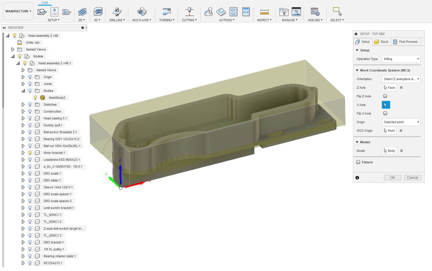
Here's the CAM for the top side:


Pretty fiddly picking up the stock origin. I placed this on a machined corner, noting that the flat surface I was picking up on was 0.47mm left of the origin:


I need to get the original position right to avoid misalignment between the top and bottom operations. I've got a 20mm gauge block up against the end of the machined face (X axis). And I can pick up the Y and Z axes from the faces of the spacer plate. 


Right, that worked out nicely. No tool breakages so far....


The witness mark between the top and bottom setups is minimal. It's less than the 10um or so I can measure with a std digital caliper. 

Now for a cover....

Bottom side CAM operations for MkII Z axis motor bracket / housing

The basic design concept:
Perhaps a bit more detailed than the title suggests. Here's what I planned.... 

Bottom view:


Section view:


Front view:


 CAM operations for bottom side:


 The part is hiding inside this piece of stock:


It should look like this after the bottom operations are complete:


Now to save the stock model, ready to turn it over and machine the top side:


Some swarf action:


And indeed it does look like the simulated part:


Although the machine was a bit overrun with swarf afterwards....


Saving CAM simulation stock for next operation

Using part-machined bodies for the next CMC setup:
How to save simulated stock as solid for use in next setup. Or another explanation.

But there's a better way, shown here by John Saunders:


They could do with making this a bit more seamless. If that saving the file, inserting it into the design as a mesh and then referencing it as a body worked best. Trying the NYCCNC method resulted in a bizarre error message about the model not being closed or somesuch. Interestingly, there was a bug fix in yesterday's update that seems to suggest a problem relating to stock models and mesh bodies.


This works well. After finally running the part (hence including any final finessing of the toolpaths), you can save the part-machined component as a solid (mesh) and then use this as the stock model for the next setup:

  • On the simulated part, right click to save the stock model. 
  • Then import it into Fusion (Insert > Mesh). 
  • Finally, in CAM setup for the next setup, choose stock from model and select the mesh body from the component tree. 
Sorted.

Thursday, 6 June 2019

Centroid Zref, part and tool length offsets - notes to self

Tool length offsets and work coordinate setting:
Got my knickers in a twist trying to recall how to set up tools and parts. It's not rocket science but that's no consolation.

Here's cnckeith explaining Zref and tool length offsets.


It's a bit confusing to be mixing a Renishaw probe in with this business. I have both a TT-type tool setter and a Renishaw probe. For tool length offsets, it expects to use the TT device. For work offsets, it defaults to the probe. 

Part offsets:
The important bit is choosing "Auto" for work (WCS) position setting, not "Probe". With the latter, the probe will withdraw by a configured amount (1mm on my system currently), so if you choose to manually zero the relevant axis at this point, you'll end up with an offset. If you use "Auto" for part position setting, not only will it not introduce and offset but it will also zero the axis for you.

Zref and tool length offsets:
The idea is to avoid having to remeasure all the offsets each time you move the table / knee vertically. Keith explains that fairly well. It's fairly simple - each time you move the knee, you fit the Ref tool (T1 in my case) and run the "Zref" "Auto" procedure. This will acquire the G53 machine z coordinate.

Switching between displaying machine coordinates and work coordinates:
Type "Alt-D" to switch. Simple enough but vuried away in the manual....

Get those tube bender brackets finished!

Last time, I'd drilled and bored out the brackets for the bearing and ballnut. To complete these parts and approach the point of assembl...